Texas Instruments
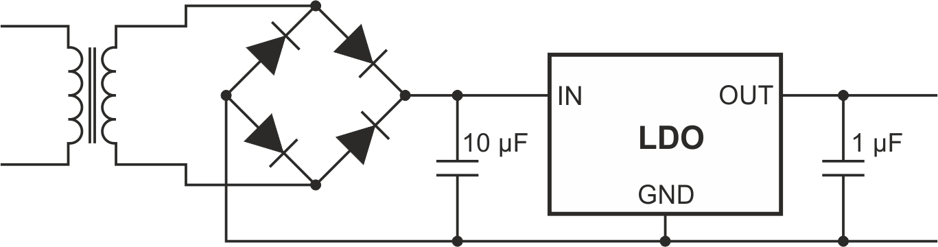
When creating an industrial power supply, one of the most common challenges is transforming the AC voltage supply into a DC voltage supply. Changing an AC voltage to a DC voltage is necessary for nearly every application, from charging cellphones to powering a microcontroller for a microwave. Typically, this conversion occurs through the use of a transformer and a rectifier, as shown in Figure 1. In this circuit, the voltage is stepped down through the transformer by a factor of the turns ratio on the primary and secondary sides of the transformer.
 |
||
| Figure 1. | Simplified AC to DC conversion using a transformer and LDO. | |
There are several drawbacks to a magnetic solution. As you probably know a transformer works by converting magnetic flux into an electrical current. As a result of this conversion, the transformer produces a lot of electromagnetic interference (EMI). The transformer also has a very noisy output voltage and needs a large capacitance to filter out that noise. For low-power applications, a more simple and cost effective approach can be used that eliminates the magnetic components. Much like how two resistors create a voltage divider, you can use a capacitor to create an AC impedance (reactance) that will drop the voltage before it reaches the power supply. This configuration is commonly referred to as a capacitive drop solution.
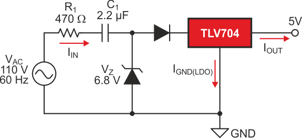
A basic capacitor drop solution will require a Zener diode to sink the required current for the application when the load is not on. This Zener diode is necessary so that the input voltage of the linear regulator (LDO) does not exceed the absolute maximum rating.
One of the drawbacks of the capacitive dropper topology is that it is not very efficient, as a lot of the power dissipates as heat on the resistor and LDO. Even when the LDO is not regulating, efficiency is still poor due to the energy dissipated in the Zener diode.
 |
||
| Figure 2. | Basic capacitive dropper circuit with an LDO for 110 VAC, 5 VDC and 30 mA. | |
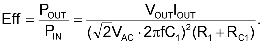
To improve the efficiency of this system, you will need to optimize three main components: the surge resistor, the Zener diode and the dropout of the LDO. Equation 1 shows how to calculate the efficiency of the basic capacitive drop solution shown in Figure 2.
 |
(1) |
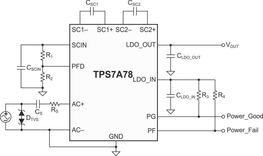
Because the cap drop solution is such a common power-supply configuration in Industrial applications such as e-metering and factory automation, TI has developed a component focused around optimizing the efficiency and solution size of a capacitive drop architecture. The TPS7A78 integrates many of the discrete components required to implement a capacitive dropper circuit, like the active bridge rectifier. Being designed to specifically operate using a capacitive drop circuit, the TPS7A78 can integrate several features that improve overall system efficiency. For example, the TPS7A78 incorporates a switch capacitor stage that reduces the input voltage by a factor of four, thus reducing the input current by the same ratio and facilitating the use of a smaller capacitive drop capacitor. This feature enables a smaller solution size, lowers system cost and reduces standby power.
 |
||
| Figure 3. | Cap drop solution using the TPS7A78 at 30 mA. | |
To understand how much better the efficiency can be using the TPS7A78 over a cap drop stage and Linear Regulator let’s compare the traditional solution shown in Figure 2 with the TPS7A78 solution shown in Figure 3. In the traditional cap drop solution using a Linear Regulator the system has an efficiency of 11%. The TPS7A78 when configured to power the same load is able to achieve an efficiency of >40% due to the reduced input current from the switch cap and the need for a smaller surge resistor.