John Bradnam
hackster.io
Use the latest ATtiny processors in the Arduino Environment. These have the memory capacity of ATmega chips in smaller and cheaper packages.
Things used in this project
- Hardware components:
- Microchip ATTiny1614, 14 Pin SOIC package ×1
- 4K7 1/4 watt resistor × 1
- Capacitor 10 µF × 1
- Arduino Nano R3 × 1
- Software apps and online services: Arduino IDE
- Prototyping Kit, Breadboard
Story
You may be familiar with the ATtiny series of microprocessors from Microchip such as the ATtiny85 or ATtiny2313. These chips powered small systems like the Digispark series. Unfortunately, they had limited Flash (usually no more than 8 K) and even more limited RAM (usually less than 1 K).
Now a new series of ATtiny chips are available with more memory and functionality. They even compete with the more expensive and larger ATmega range of chips. The ATtiny1614 that I will be looking at has 16 KB Flash Memory and 2 KB RAM in a 14-pin SOIC package (Figure 1).
 |
|
| Figure 1. | Using the New ATtiny Processors with Arduino IDE. |
Using a breadboard
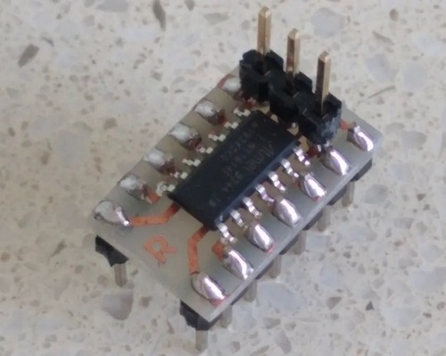
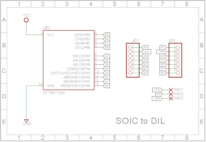
One of the problems with experimenting with these new chips are that they only come as Surface Mount Devices (SMD). This makes it hard to use on a breadboard. I have made a simple adapter board that allows a ATtiny1614 chip to be used as standard Dual-In-Line (DIL) device (Figure 2).
 |
|
| Figure 2. | Schematic Diagram of a simple adapter board that allows a ATtiny1614 chip to be used as standard Dual-In-Line device. |
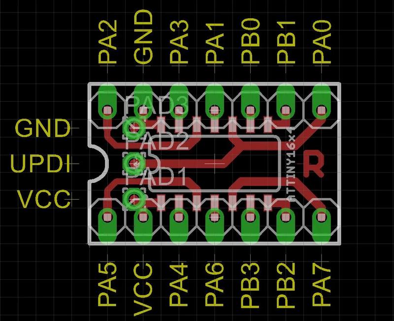
The Eagle files have been included should you wish to get the adapter board commercially made or you can make it yourself (Figure 3). I made mine using the Toner method. Note: The DIL pin layout differs from the SMD pin layout. I did this on purpose so I could use a single sided PCB and keep the 0.3 in width. The UPDI/RESET, VCC and GND pins have there own separate header so that a programmer can be connected to the board even when the adapter has been soldered into another PCB.
 |
|
| Figure 3. | Eagle PCB design for ATtiny1614 SOIC-to-DIL adapter board. |
Programming the new ATtiny processors
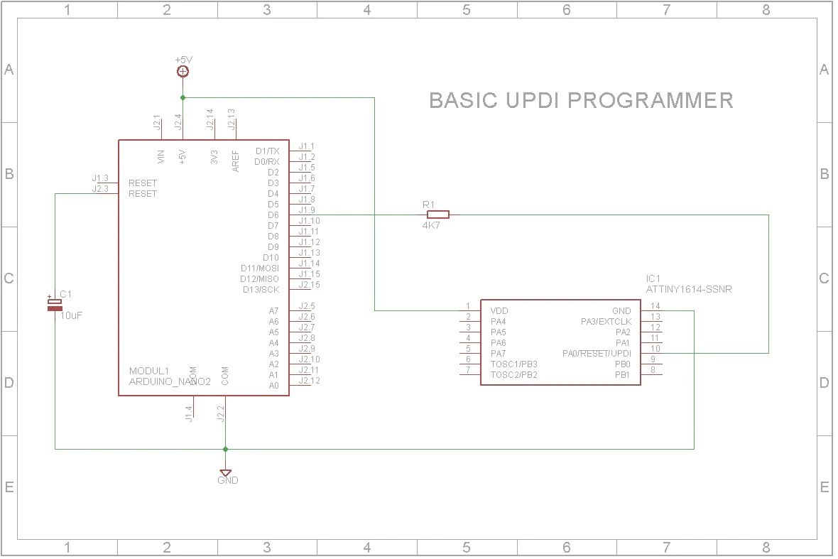
One of the biggest changes in these processors is the way they are programmed. They use a system called Unified Program and Debug Interface (UPDI for short). This interface uses the RESET pin to program and/or debug the device. In this tutorial I will be using a Arduino Nano to send the correct signals to UPDI/RESET pin (Figure 4). Once the processor is programmed, the Arduino Nano is no longer required.
 |
|
| Figure 4. | Schematic Diagram for Arduino Nano as a UPDI programmer for ATtiny1614. |
Step 1: Setting up the Arduino as a programmer
- Unzip the attached "SpenceKonde - jtag2updi.zip" file into your Arduino program folder and program the Arduino Nano. Note: It's OK that the jtag2updi.ino file is empty as the actual code resides in the other files.
- To stop the Arduino Sketch being over-written when you program the ATtiny, you need to disable the RESET line on the Arduino. You do this by adding a 10 uF capacitor between RESET and GND. A short reset pulse will only reset the ATtiny and not the Arduino. You can still RESET the Arduino by holding down the RESET button for a longer time.
- Connect a 4K7 resistor between D6 on the Arduino and the RESET/UPDI pin on the ATtiny as shown in the schematic above. Also add the +5 V and GND connections from the Arduino Nano to power the ATtiny.
Step 2: Installing the megaTinyCore in the Arduino IDE
This board package can be installed via the board manager. The boards manager URL is: http://drazzy.com/package_drazzy.com_index.json
- File -> Preferences, enter the above URL in "Additional Boards Manager URLs"
- Tools -> Boards -> Boards Manager...
- Select "megaTinyCore by Spence Konde" and click "Install".
Step 3: Select the programmer
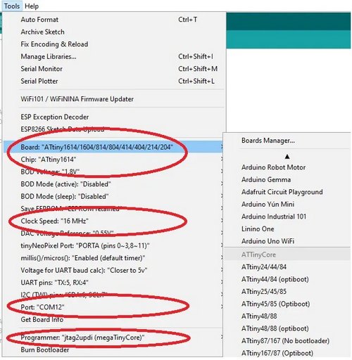
Once the board has been installed in the IDE, select it from the Tools menu (Figure 5).
 |
|
| Figure 5. | Select board type for Attiny1614 in Arduino IDE. |
Make sure you select the Chip that you are about to program. Also libraries such as the Adafruit Neopixel Library won't work on a 20 MHz clock so you may need to wind the clock speed back to 16 MHz or 8 MHz if you are running the chip from a 3V3 supply.
The Programmer needs to be set to jtag2updi (megaTinyCore).
Pin mapping and the Arduino IDE
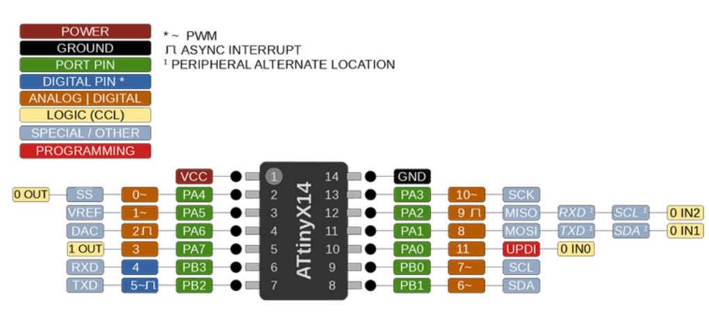
To access the physical IO pins in the Arduino IDE using digitalRead, digitalWrite, analogRead or analogWrite, use the pin map above to determine the pin number to use (Figure 6). Note: Unlike the ATmega328, the new ATtiny processors don't have separate analog pins. Whether a pin is analog or digital depends on which function you use to access it.
 |
|
| Figure 6. | ATtiny1614 Pin mapping and the Arduino IDE. |
Blink Example
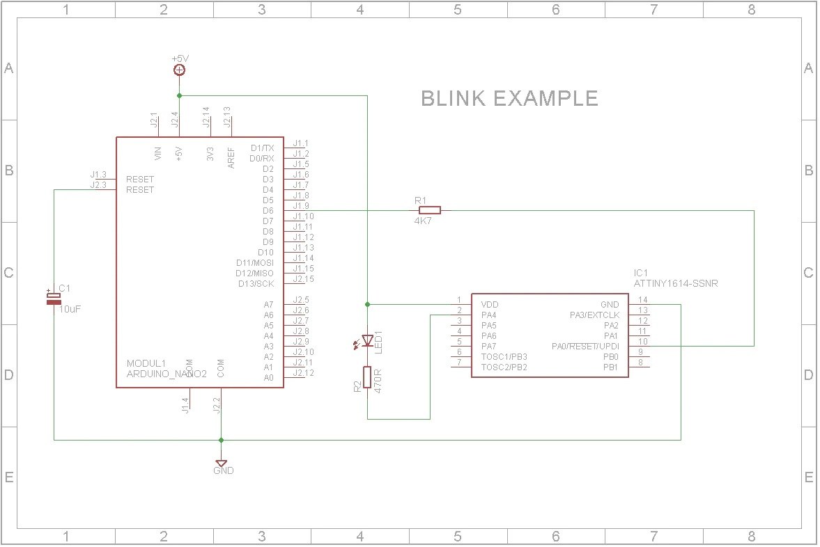
To test the programmer, wire a LED and 470 Ohm resistor between pin 2 (PA4) of the ATtiny1614 and +5 V (Figure 7). Open the Blink_ATTiny1614.ino file in the Arduino IDE and select "Upload using programmer" from the Sketch menu. Ignore the error message "avrdude: jtagmkII_initialize(): Cannot locate "flash" and "boot" memories in description".
 |
|
| Figure 7. | ATtiny1614 Blink Example Schematic Diagram. |
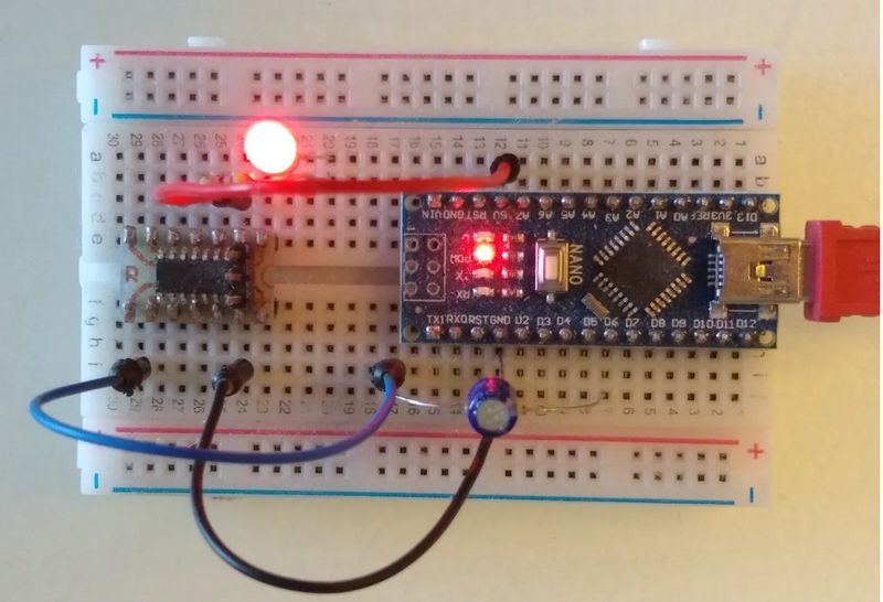
The LED should start to blink (Figure 8).
 |
|
| Figure 8. | ATtiny1614 Blink Example on breadboard. |
Note: Physical pin 2 (PA4) is D0 in the Arduino IDE
Color changer example
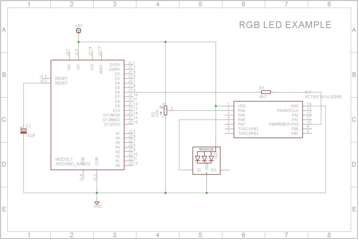
In this example, I will use the Adafruit Neopixel library to control a WS2812B led via a potentiometer (Figure 9). (I used a 10 K potentiometer but any value from 1 K to 100 K will work in this case).
 |
|
| Figure 9. | ATtiny1614 Color Change Example Schematic Diagram. |
Conclusion
With the extra Flash and Static RAM incorporated in these new ATtiny processors, not to mention the new internal component features, it opens new doors for even smaller projects. I think you will find that it will be worth-while reading the datasheets for these new processors. It could be the start of your next exciting project.