While measuring op-amp input capacitance, what should you focus on? The answer is that you must ensure the measurement accuracy isn’t degraded by the stray capacitance and inductance of the PCB or test setup. You can minimize these issues by using probes with low capacitance, using short lines on the PCB, and avoiding huge ground planes below the signal traces.
Operational amplifiers are employed in a wide variety of electronic circuits. Their task is to amplify small electrical voltages for further signal processing. Applications such as smoke detectors, photodiode transimpedance amplifiers, medical instruments, and even industrial control systems require the lowest possible op-amp input capacitance. That’s because, among other things, it affects the noise component, which in turn affects system stability, especially for systems with high frequencies and gains.
To maximize the accuracy of a corresponding circuit, it’s necessary to know the input capacitance of the op amp. Datasheets, however, often don’t provide this information, so it must be independently determined. And that can be difficult because the input capacitance in many cases is only a few picofarads.
The Table 1 lists a few different examples of operational amplifiers and their respective input capacitance values.
| Table 1. | Different op amps and their input capacitance values | ||||||||||||||||||
|
|||||||||||||||||||
How to Determine Input Capacitance
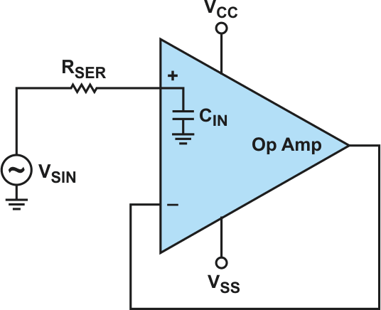
An easy way to determine the input capacitance of an op amp is to add a resistor in series (RSER) with the op-amp input (Fig. 1). This yields a first-order low-pass filter with a frequency response that can be recorded by a network analyzer. The input capacitance can be calculated from the frequency response. The resistance RSER is typically in the range of 10 to 100 kΩ.
 |
|
| Figure 1. | With a series resistor at the op-amp input, the input capacitance of the op amp can be measured. |
When recording the frequency response, you must ensure that the measurement accuracy isn’t degraded by the stray capacitance and inductance of the PCB or test setup.
A high measurement resolution should be selected for minimal stray capacitance. The use of low-capacitance FET probes (<1 pF) is advisable.
The PCB capacitance with respect to ground also should be kept as low as possible. This can be achieved by ensuring that there’s no ground plane below the signal traces and the series resistor.
In addition, the shortest possible lines and (resistor) leads should be used to avoid additional sources of error, such as series and parasitic inductance.
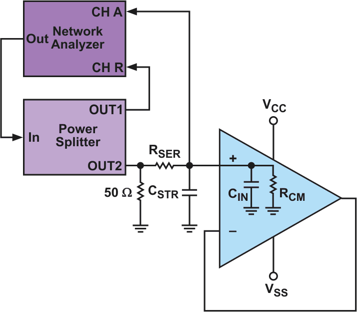
Figure 2 shows a possible test setup, using a network analyzer and a power splitter.
 |
|
| Figure 2. | Shown is a test setup for determining the op-amp input capacitance. |
The power splitter has the task of dividing the signal. The signal 1:1 is fed unchanged to the input of the network analyzer and passed through the inserted low-pass filter to the op-amp input. The network analyzer then generates the frequency response from the difference between these two signals.
Making the Measurement
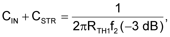
For the measurement itself, the stray capacitance (CSTR) must be determined. To do this, the signal is applied without the op amp on the board. From the resulting Bode plot, CSTR is calculated as shown in Equation 1:
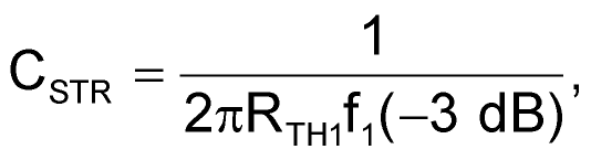 |
(1) |
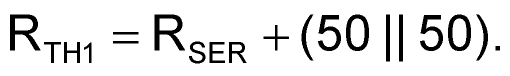
where f1(–3 dB) is the –3 dB corner frequency measured with the network analyzer without an op amp, and RTH1 is a function of the inserted series resistance (RSER), the input termination resistance (50 Ω), and the 50-Ω source impedance at the power splitter (Thévenin equivalent):
 |
(2) |
Next, the op amp is placed on the printed circuit board (PCB).
Because the stray capacitance of the PCB is in parallel with the input capacitance of the op amp, Equation 1 is supplemented with CIN as shown in Equation 3:
 |
(3) |
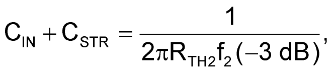
This time, f2(–3 dB) is the –3 dB corner frequency measured by the network analyzer with an op amp and RTH2 is a function of the inserted series resistance, the input termination resistance (50 Ω), the output impedance of the power splitter (50 Ω), and the common-mode input impedance of the op amp (RCM):
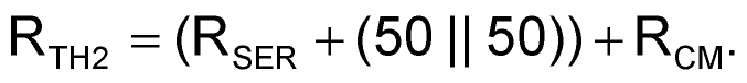 |
(4) |
In general, for op amps with CMOS inputs, RSER << RCM. Therefore, RTH2 ≈ RTH1 and Equation 3 can be rewritten as shown in Equation 5:
 |
(5) |
The input capacitance of the operational amplifier can then be determined using Equations 1 and 5.
Conclusion
The input capacitance of an op amp can be difficult to measure. It often lies in the picofarad range and parasitic effects in the test setup distort the result. But with a small test setup and the appropriate measuring equipment consisting of a network analyzer and a power splitter, it’s easy to determine the input capacitance.
First determine the stray capacitance (error capacitors in the test setup) and then determine the combined capacitance (error capacitors and input capacitance) of the op-amp circuit via the frequency response. With the equations shown earlier, the actual input capacitance of the operational amplifier can be calculated.