Most designers consider slowness in diodes to be an imperfection or a limitation. Why not take a more positive view of the situation? After all, a zener or an avalanche diode is no more than a diode with a limited breakdown voltage, and you can view a varactor as a diode with a large and nonlinear parasitic capacitance. Similarly, could you view the slowness of a diode as a property or even a feature? For example, consider a PIN diode. Few people are aware that the key property of a PIN diode is indeed its slowness; without it, it would generate large amounts of distortion and require a larger control current to function properly. You can put this ability of slow diodes to store large amounts of electrical charge to good use in a variety of other circuits. Figure 1 shows how to generate dead time using such diodes. A PWM sandcastle (stepped) waveform feeds a half-bridge.
 |
|
| Figure 1. | You can use slow diodes to generate dead time in a half-bridge configuration. |
In a classical implementation, you must insert dead time in the control circuitry to avoid the simultaneous conduction of the two transistors when the duty cycle approaches 100%. This dead time is a standard feature of PWM-control ICs. If you use slow diodes for D1 and D2, you need no dead time. If, for example, Q1 receives a positive base, or gate, drive and is therefore conducting, D2 becomes forward-biased. When the control signal reverses its polarity, a negative bias appears immediately on Q1, but D2 cannot instantly cease conducting and short-circuits the base drive to Q2 during all of its reverse recovery time. The advantage of generating a dead time in this way lies in the fact that you need include only a small safety margin: The phenomena governing the recovery time of a diode are similar to those resulting in storage times in power devices. both display a strong positive-temperature coefficient, for which this scheme compensates. The ability to operate at duty cycles close to 100% allows a better usage of the power components, translating into savings and higher performance: A universal-input supply, for instance, can operate at lower supply voltages.
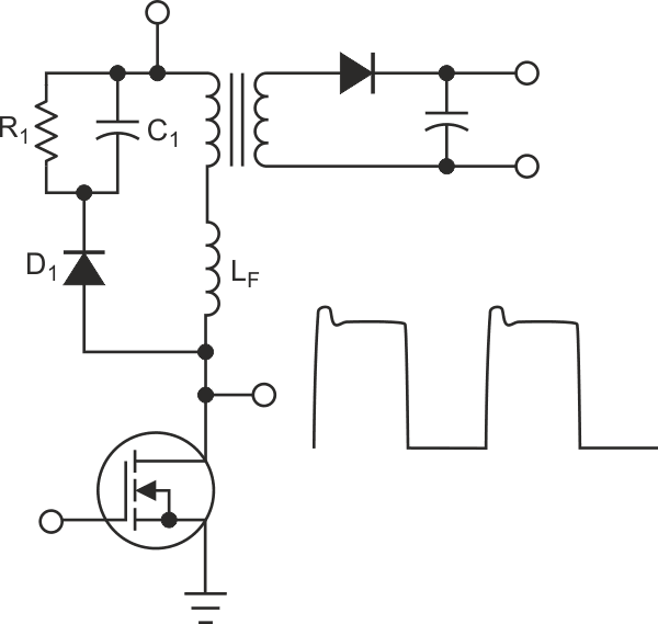
Figure 2 shows another example. This standard clamping circuit protects the switching transistor of a flyback converter against the voltage spike generated by the imperfect coupling between the primary and the secondary windings of the transformer. In an equivalent schematic, this scenario translates into a leakage inductance, LF, in series with the primary winding. The circuit works in the following way: Each time the transistor turns off, the current in the leakage inductance continues to flow, but D1 intercepts it and “redirects” it to C1. C1 has a large enough capacitance that cycle-to-cycle variations do not influence it. The average voltage on C1 results from a balance between the charging input from the leakage inductance and the current that bleeds from R1. Usually, D1 is a fast diode, but, if you substitute it with a slow one, interesting things happen: Instead of switching off when the voltage on C1 reaches its peak, D1 continues to conduct, thus transferring back charge and energy from C1 to the transformer and ultimately to the load. The overall efficiency is therefore better, and R1 can have higher resistance and can be smaller. Added to the lower cost of a standard diode versus a fast one, the method provides non-negligible benefits.
 |
|
| Figure 2. | In this circuit, a slow diode protects the switching transistor from destructive voltage transients. |
It is preferable to select a diode with a recovery time as long as possible. Popular types, such as the 1N400x series, have recovery times of approximately 2.5 µsec, but some models reach more than 5 µsec. Ideally, C1 and LF should resonate at a period equal to twice the diode's recovery time. When the component values are nearly optimum, R1 can have a large value, its only role being to provide a “seed” current to prime the circuit. You pay a small penalty for these advantages: The peak clamping voltage increases by several volts, because you must add the positive cycle of the resonance to the average clamping voltage and because slow diodes often exhibit a slightly poorer forward-recovery characteristic than do their fast counterparts. This characteristic results in a step of several volts at the beginning of the conduction.
Normally, these small snags should pose no problem; you can substitute the new components in a design without any other change. The circuits in Figure 1 and Figure 2 are only two examples, but you can apply the same useful principles to a variety of other circuits.