Particulate matter (PM2.5) monitoring is a key public-health metric. Vehicle- and drone-mounted sensors can expand coverage, but many existing systems are too costly for broad deployment. This Design Idea (DI) presents a prototype PM2.5 sensing and power-generation front end for a low-cost, batteryless, vehicle-mounted node.
Two constraints drive the circuit design:
- Minimizing power to enable batteryless operation
- Harvesting and regulating power from a variable source
Beyond choosing a low-power sensor and MCU, the firmware duty-cycles aggressively: the PM2.5 sensor is fully powered down between samples, and the MCU enters deep sleep. A high-side MOSFET switch disconnects the sensor supply and avoids the ground bounce risk of low-side switching.
Low-cost micro wind turbines can harvest energy from vehicle motion, but available power is limited at typical road speeds, and the output voltage varies with airflow. A supercapacitor provides energy buffering, while a DC-DC buck converter clamps and regulates the rail for reliable sensor/MCU operation.
The circuits were built and tested, and the results highlight current limitations and next steps for improvement.
PM2.5 sensor and MCU circuit
Figure 1 shows the sensing schematic: a PM2105 PM2.5 sensor, an ESP32-C3 module, and an FQP27P06 high-side PMOS switch.
 |
|
| Figure 1. | Sensing circuit schematic with a PM2105 PM2.5 sensor, an ESP32-C3 module, and an FQP27P06 high-side PMOS switch. |
Calculating the power budget
A PM2105 (cubic sensor and instrument) was chosen for low operating current (53 mA) and fast data acquisition (4 s). To size the batteryless budget, we measured total sensing-circuit power (PM2105 plus ESP32-C3) using an alternating on-and-standby test pattern (Figure 2).
 |
|
| Figure 2. | Sensing circuit power consumption in operating and standby mode. |
Power peaks during the first ~4 s after sensor power-up and during sensor operation. This startup transient occurs as the sensor ramps the laser intensity and fan speed to stabilize readings. With a 5-V supply, the measured average power is ~650 mW for the first 4 s and ~500 mW for the remaining on interval. In standby, power drops to ~260 mW, with most consumption from the MCU.
Because the PM2105 settles in ~4 s, the firmware samples for ~4 s, then switches the sensor off and puts the MCU into deep sleep until the next sample time.
Operating and deep sleep modes
The MCU is based on Espressif Systems’ ESP32-C3, a low-power SoC. It controls the sensor, acquires PM2.5 data, and transmits it to the vehicle gateway, router, or portable hotspot. Both devices support I2C and UART, but UART was used to tolerate longer cable runs in a vehicle.
To fully remove PM2105 power between samples, an FQP27P06 PMOS high-side switch disconnects VCC (Figure 1). A low-side switch would also cut power, but digital switching currents can create ground IR drop and ground bounce. In sensing systems, ground noise is typically more damaging than supply ripple. FQP27P06 was selected for low on-resistance and high current capability.
In deep sleep mode, the MCU GPIOs float (high impedance). A 33 kΩ pull-down and an inverter force the PMOS gate to a defined OFF state during sleep. Because the ESP32-C3 uses 3.3 V GPIO, the high-side gate drive needs level shifting. A TI SN74LV1T04 provides both inversion and level shifting in one device.
Batteryless power generation
Wind turbine
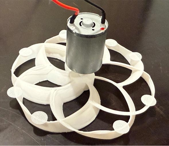
Vehicle motion provides airflow, making a micro wind turbine a convenient harvester. A small brushed DC motor and rotor act as the turbine (Figure 3). Assuming vehicle speeds of ~15 to 65 mph, a representative average headwind speed is ~30 to 40 mph.
 |
|
| Figure 3. | Micro wind turbine comprising a DC motor and rotor. |
At 35 mph, the turbine under test delivered ~3.2 V and ~135 mW into 41 Ω, selected to approximate the average MCU and sensor load. That output is insufficient for a regulated 5-V rail and the ~650-mW startup peak.
Supercapacitor
To bridge this gap, a 10-F supercapacitor stores energy and buffers the turbine from the sensing load. Because turbine output varies with speed and the MCU and sensor maximum voltage must remain below 5.5 V, the turbine cannot be connected directly to the sensing circuit. We used an LM2596 adjustable buck-converter module set to 5 V to keep the voltage within limits.
Figure 4 shows the power-generation schematic. A series Schottky diode (D1) protects the buck stage if the turbine reverses polarity during reverse rotation.
 |
|
| Figure 4. | Power-generation system where a series Schottky diode (D1) protects the buck stage if the turbine reverses polarity during reverse rotation. |
During sensor operation, the supercapacitor supplies load current. The supercapacitor droop per sample is:
where I is the average operating current, and T is the operating time per sample.
When the sensing circuit is on, the turbine voltage can fall below 5 V, for example, ~3.2 V at 35 mph, and the LM2596 output correspondingly drops. Because LM2596 is an asynchronous (diode-rectified) buck converter, reverse current is blocked when the converter output falls below the supercapacitor voltage, preventing the supercapacitor from discharging back into the converter.
After sampling, the sensor is powered down, and the MCU enters deep sleep. With the load reduced, the turbine voltage rises. At 35 mph, the turbine produces ~9 V while charging a 10 F supercapacitor through the LM2596 with no additional load.
The buck output regulates at 5 V and charges the supercapacitor. Near 5 V, the measured charge rate is ~2.3 mV/s. Therefore, the time to recover the ~50 mV droop from a sample is:
This supports ~30 s sampling at ~35 mph. Vehicle speed variation will affect the achievable sampling rate, but for public health PM2.5 monitoring, update intervals on the order of 1 minute are often sufficient.
Results and future work
 |
|
| Figure 5. | Prototype sensing circuit board with the PM2105, ESP32-C3 circuitry, and a 10-F supercapacitor. |
Figure 5 shows the prototype sensing PCB with the PM2105, ESP32-C3 circuitry, and a 10-F supercapacitor on the same board. Figure 6 shows the LM2596 buck module configured for a 5-V output.
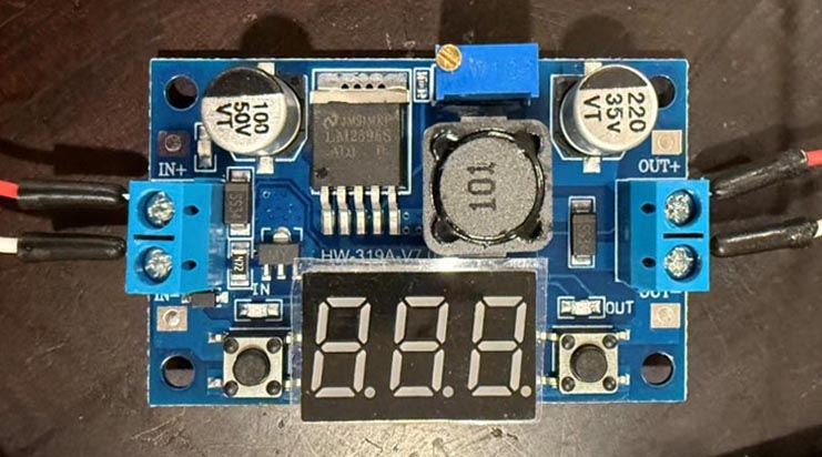 |
|
| Figure 6. | LM2596 DC-DC down-converter configured for a 5-V output. |
A steady wind supply provided continuous airflow at ~35 mph, verified by an anemometer, directed at the turbine blade. The MCU powered up the sensor and acquired a PM2.5 sample every 30 s. Before the test, the supercapacitor was precharged to 5 V using USB power. During the run, the system was powered only by the supercapacitor and the wind turbine.
Over a 1-hour run, the system reported PM2.5 data at a 30-s sampling interval. Table 1 shows an excerpt of the collected PM data.
| Table 1. | Excerpt of the collected PM data (sensor not calibrated) |
|
22:37:10.200 -> ----- BEGIN pm.csv ----- 1: PM1=2, PM2.5=2, PM10=2 |
|
Next, the system will be mounted on a test vehicle for road testing. One limitation is the micro wind turbine’s low output power. Once the supercapacitor is charged to 5 V, the system can sustain operation, but initial charging using only the turbine is slow. With a 10-F supercapacitor, the initial charge time can be on the order of ~30 minutes. Reducing capacitance shortens charge time, but larger capacitance helps ride through low-speed driving and stops.
In this prototype, PM data were logged locally and downloaded over USB after the test was completed. In deployment, Wi-Fi transmission typically increases MCU energy per sample. The connection and transmission can add up to ~1 s of active time. These factors increase the required harvested power. Future work focuses on increasing harvested power using a higher-power motor, an improved rotor, or multiple turbines in parallel. The goal is a self-starting system that charges the supercapacitor within a few minutes at typical road speeds.
Reference
- Rohal, Shubham, Zhang, Joshua, Montgomery-Yale, Farren, Lee, Dong Yoon, Schertz, Stephen, & Pan, Shijia. (2025, May 6–9). Self-Adaptive Structure Enabled Energy-Efficient PM2.5 Sensing. 13th International Workshop on Energy Harvesting and Energy-Neutral Sensing Systems (ENSsys ’25).