Could a simple passive RC network without any transformers, inductors, switches, or non-linear components produce a voltage gain?
Well, it’s not “free energy,” however, yes, and can even use the same value resistor and capacitor in a ladder network shown in Figure 1, although differing values also can be utilized.
 |
|
| Figure 1. | Passive RC circuit using resistors and capacitors of the same value in a ladder network. |
Of course, this isn’t of much use other than a curiosity, but it’s a fun circuit to build and play around with!
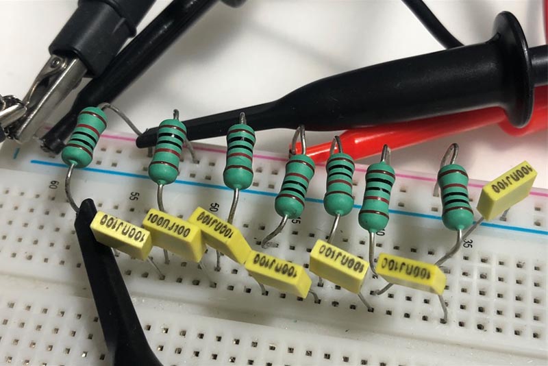
I built one with seven sections (Figure 2) using an R of 10 kΩ and a C of 0.1 µF, then plotted the results.
 |
|
| Figure 2. | A seven-section RC ladder network with an R of 10 kΩ and C of 0.1 µF. |
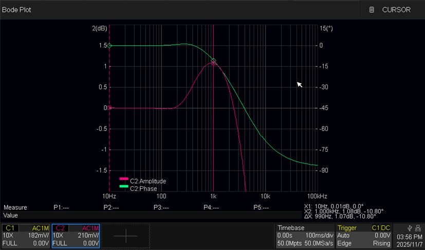
The Bode plot can be seen in Figure 3. As you can see, the gain remains around 0 dBv and behaves as a low-pass filter, then slowly rises to a peak of 1.07 dBv at 1 kHz before falling off.
 |
|
| Figure 3. | Bode plot of the passive RC circuit showing low-pass filter behavior until a slow rise to a peak of 1.07 dBv at 1 kHz.an R of 10 kΩ and C of 0.1 µF. |
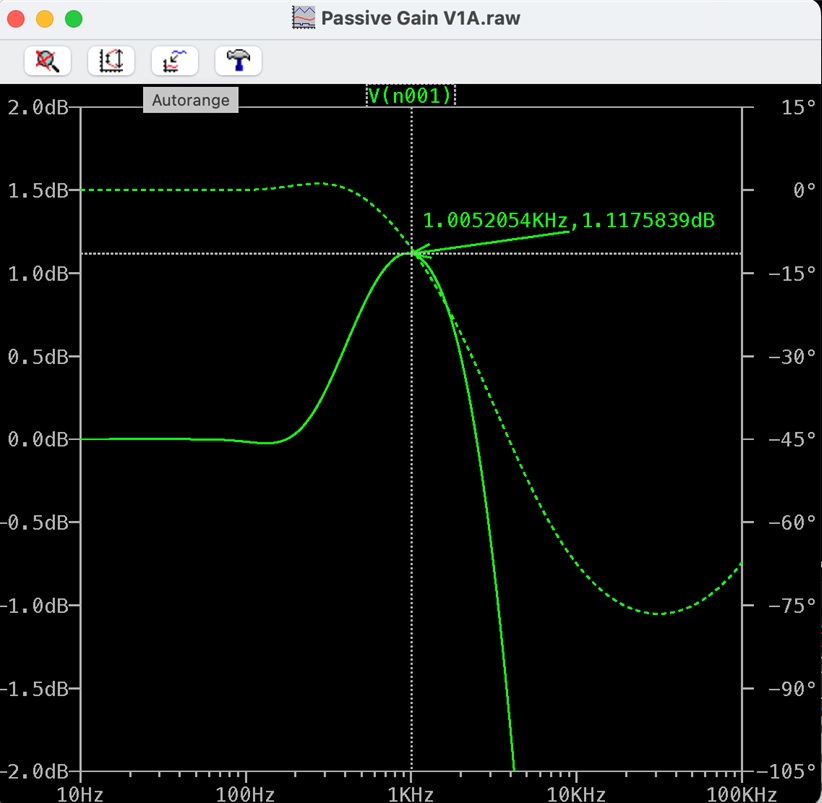
This agrees well with the simulation shown in Figure 4.
 |
|
| Figure 4. | Circuit simulation of a passive RC circuit that closely matches the Bode plot shown in Figure 3. |
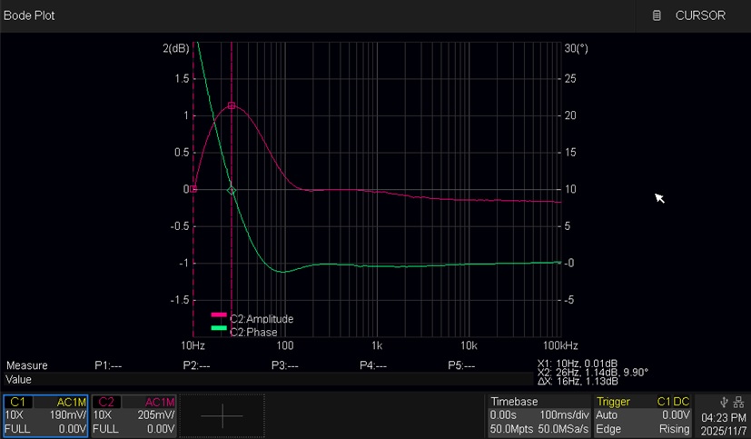
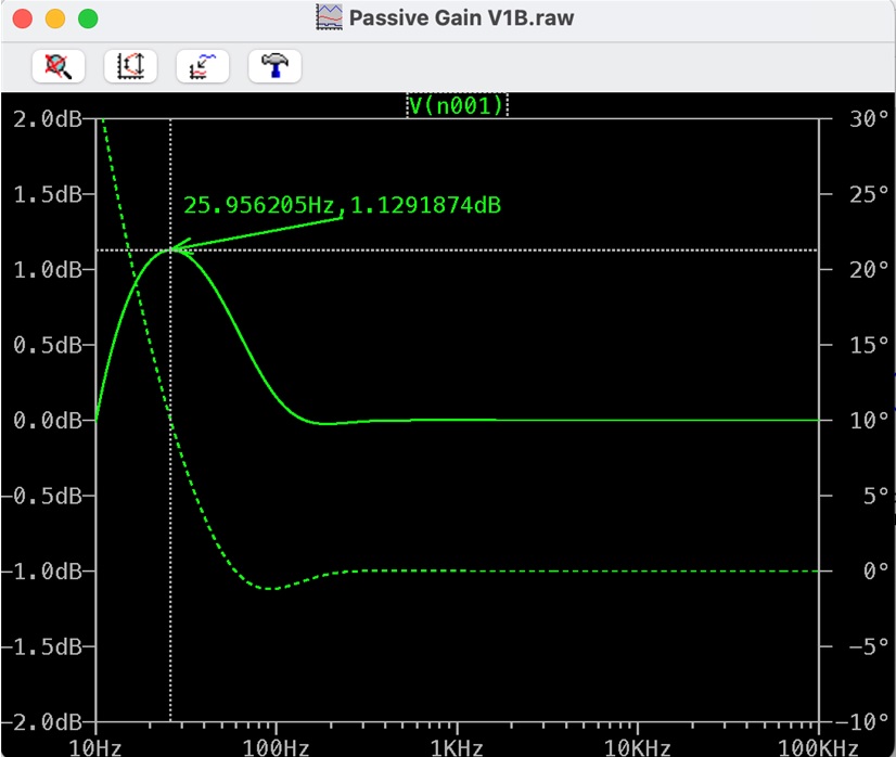
If you swap the resistors and capacitors, the circuit behaves like a high-pass filter and produces a higher gain of 1.13 dBv at 26 Hz, as shown in Figure 5, and a simulation in Figure 6.
 |
|
| Figure 5. | Bode plot of the passive RC circuit showing high-pass filter behavior. |
 |
|
| Figure 6. | Circuit simulation of a passive RC circuit that closely matches the Bode plot shown in Figure 5. |
As noted by someone, this technique can be employed with an emitter-follower, which has a voltage gain less than unity to create an oscillator. However, that’s for another upcoming Design Idea (DI), which will also include a note on how a single unbiased JFET can produce a +dBv voltage gain!
Anyway, hopefully some folks find this interesting and have some fun!