The characteristics of the battery, especially the capacity and variation of the voltage on discharge, are needed to be known for circuit design of the battery powered equipments. The technical data of the junk battery is not that always available so that it must be measured by user. But it is hard to record the data by human because the measurement of discharge characteristics takes some hours a cycle. Any data logging system is required to measure the battery characteristics. This project builds a simple automatic battery discharge analyzer.
Fundamentals and Requirements
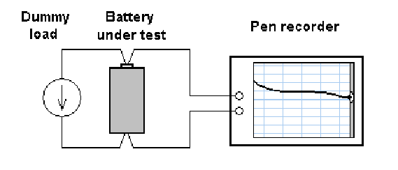
Below image shows a basic battery measurement system. It records only variation of the voltage while a discharge cycle. There is nothing difficult and it will able to be done with generic instruments but a built instrument specified for the battery measurement is better than generic one.
Follows are the implemented functions of the battery discharge analyzer to build in this project.
Load mode
Supports three different load modes, constant current, constant wattage and resistive. This enables to simulate various battery powered equipments with linear power circuit, switch mode power circuit and simple resister, lamp and heater. The constant current mode is usually used to measure typical characteristics of the battery itself.
Automatic logging
The measured data is sent to the PC and recorded to the file.
Measurement of ESR
Supports measurement of series resistance of the battery.
Building Hardware
Circuit Diagram
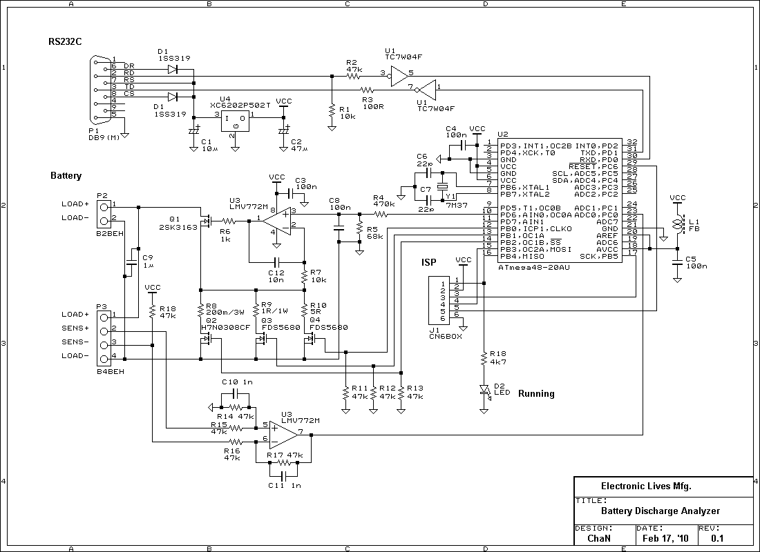
Above image shows the circuit diagram of the built battery discharge analyzer. It is controlled with a PC via a serial port. No external power supply is required because it is powered by RS-232C signals.
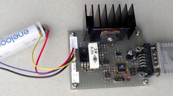
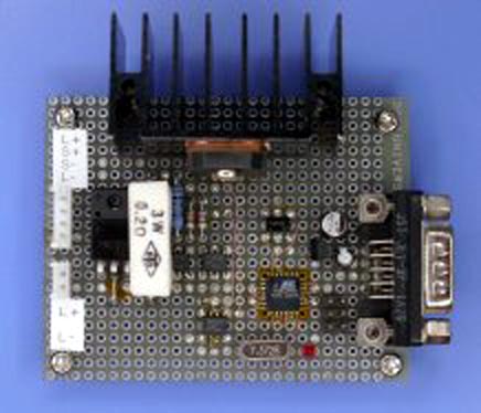
The dummy load, constant current circuit, is controlled by a microcontroller. At constant power and resistive mode, the load current is controlled dynamically to simulate the load characteristics from view point of the battery. The current range is divided in three to increase the current resolution over supported current range. The power dissipation at the control transister Q1 can become up to 10 watts at maximum load current so that a thermal control, heat sink and cooling fan, is requierd. The heat sink used in this board can work up to several watts without a fan. When the power dissipation exceeds the limit, a larger heat sink or a cooling fan will be required. The operating voltage range is 0.8 to 4.5 volts and load current is up to 3 amperes. This enables to measure Li-Ion, Ni-Cd, Ni-MH and alkaline cells.
For measurement of battery voltage, four-wire method is used to eliminate an error due to drop out voltage at the wires and contacts. This is needed at high current and low voltage cells, such as Ni-Cd and Ni-MH. I am using JST EHR-2 wire to PCB connector for my projects so that a two contact connector B2B-EH is also added on the board.
To be continued