MiniLA is a project of simple and cheap logic analyzer designed for amateur and semi-professional work.
Features:
- Up to 32 channels
- 128 Kb of memory for each channel
- Sampling rate up to 100 MHz (timebase in 1-2-5 sequence)
- External clock input
- Input levels compatible with 3.3V and 5V logic
- Selectable pretrigger/posttrigger buffer size in 8K steps
- 16 bits wide trigger (0, 1, rising/falling edge, don't care)
- Programmable min. trigger-event width (1-16)
- Programmable trigger-events counter (1-16)
- External trigger input
- Communicating via LPT port (EPP mode support) or USB
- Documentation and source codes released under GNU GPL
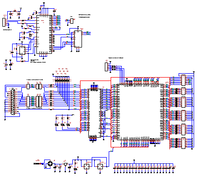
Schematic of the miniLA is shown on the picture below.
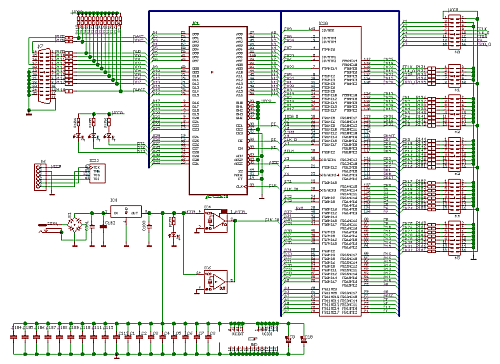
Heart of the miniLA is CPLD XC95288XL from Xilinx. This reprogrammable devices implements all of the necessary logic.
Samples are stored into fast synchronous SRAM AS7C33128.
Devices are supplied by 3.3V stabilized by LD1117DT-3.3.
Oscillator IC4(IC6) is a clock source for the CPLD. This oscillator is supplied by 3.3V. Good source for oscillators are old PC mainboards. Experiences shown, that such oscillators did not have problem to work with 3.3V power supply, although they are designed for 5V.
Next picture shows the PCB layout. Dual layered PCB uses thru-hole and SMD devices.
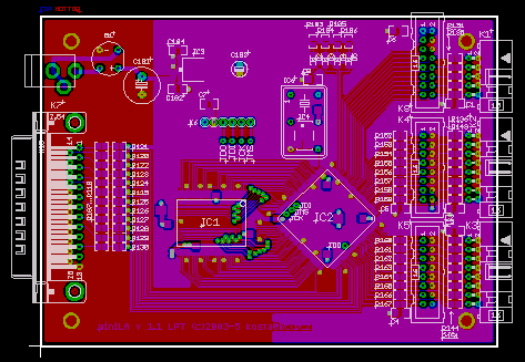
Important note:
For the EMC reasons, the connections between JTAG pins of the CPLD and the connector K6 are not made and wires need to be added.
Errata
Vss connects to pin 39 of the SRAM instead of 40. Solution - connect pins 39 and 40 (pin 39 is not used by SRAM).
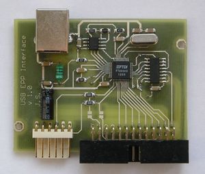
USB Interface
Version A 1.1
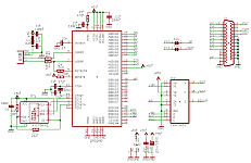
Schematic of the USB interface is shown on the picture below.
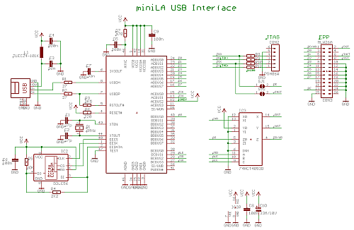
USB interface uses chip FT2232C from FTDI. Connection is recommended USB Bus powered configuration. The chip is configured to work in MCU Host Bus Emulation Mode. This mode is converted to EPP protocol by multiplexer IC3. Because direct decoding of signals /DST, /AST and RD/WR might have timing problems, supplementary signal A8 is used and acts as a RD/WR signal during EPP data phase.
JTAG connector CON2 is for CPLD reconfiguration. It is for future development and is not currently supported
EEPROM IC2 stores the configuration of the FT2232C. This EEPROM must be for correct functionality of the interface programmed. See program MPROG on FTDI website.
Drivers for FTDI USB chip are also available on FTDI website.
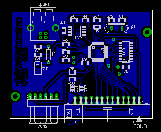
PCB of the interface shown on the picture above uses dual-layered PCB. Since there are only 6 vias the PCB can be made at home with vias replaced by wires.
Version B 1.0
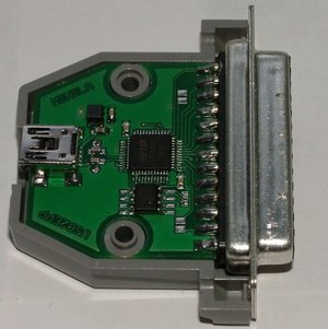
USB interface also exists in version B. This version uses different PCB layout. It does not have separate JTAG connector and it fits into CANNON 25 connector cover.
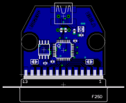
Pictures of version A 1.0 and version B 1.0
Hardware - Other versions
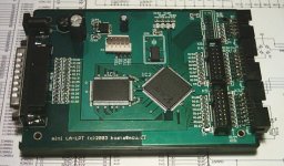
miniLA by Bob Grieb
This version of the miniLA PCB integrates both LPT and USB interfaces on one board.
Schematic is shown on the picture below.
The tool used for schematic is TinyCAD and PCB was designed in FreePCB.
Part 2 - Firmware, Software
Downloads
Hardware v.1.1 - Whole package (schematic, device placement, Gerber, Excellon and PS data for PCB) - download
Hardware by Bob Grieb - Whole package (schematic, PCB, device placement) - download
USB interface A1.1 - Whole package (schematic, device placement, Gerber, Excellon and PS data for PCB) - download
USB interface B1.0 - Whole package (schematic, device placement, Gerber, Excellon and PS data for PCB) - download