Part 1 - Theory
Circuit diagram
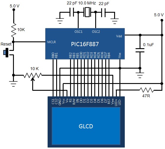
The circuit diagram for this experiment is shown below. The PIC16F887 microcontroller is used to drive a Winstar WDG0151-TMI GLCD. The data pins are connected to PORTD and other control signals are driven through PORTB pins. I am trying this circuit on MikroElektronika’s UNI-DS6 development board.

Connecting GLCD to microcontroller
Software
We will be writing our test program in C using MikroElektronika’s mikroC Pro for PIC compiler. Although, the compiler does provide built-in library routines for GLCD operations, we will first try to write our own test code for transferring display data from the PIC16F887 to the GLCD. Later, we will explore the MikroElektronika’s GLCD library for more complex operations. The code provided below generates 11 dotted horizontal lines on the GLCD screen with a six-line spacing between two. I took most portion of it from Osama’s Lab GLCD library and modified it to suit with mikroC Pro for PIC and WDG0151-TMI GLCD. Here’s a brief description of various user-defined function subroutines used in the code.
- GLCD_ON(): This function turns the display on. This can be done by sending the command 3Fh to both the controllers. So, while sending this command, both CS1 and CS2 must be pulled low. Similarly the RS pin should be low too as the byte sent is an instruction.
- Set_Start_Line(): This function changes the line number to be displayed at the top of the screen. You can set it to be any number between 0 to 63. It does not affect the data in the display RAM, it just scrolls the display up and down.
- GOTO_COL(): Moves the cursor to specified column (0-127).
- GOTO_ROW(): Moves the cursor to specified row or page number (0-7).
- GOTO_XY(): Moves the cursor to specified row and column.
- GLCD_Write(): Writes a byte of data to the current location.
- GLCD_Read(): Returns a byte read from the current display location. If you see the code for this subroutine, you will see there are two read operations involved. The first one is a dummy read during which the data is fetched from the display RAM is latched in to the output register of KS0108B. In the second read, the microcontroller can get the actual data.
- GLCD_Clrln(): Clears a specified row (0-7).
- GLCD_CLR(): Clears the whole screen (all 8 pages).
- Draw_Point(): Plots a dark or light color point at a specified position.
At the end, the dotted lines are created by plotting too many points in horizontal directions.
Downloads
Source code and HEX file - download
UNI-DS6 Schematic Diagram - download
Part 3 - GLCD Library of mikroC Pro for PIC