Part 1 - Schematic
Firmware
The entire firmware relies on logical decisions at every step. I wrote the code in a way that the complete code is divided into understandable small functional blocks or functions. Each of these functions is doing specific tasks.
Starting from the top of the code, I declared some definitions of port pins, LCD pins and EEPROM locations. Next I declared global variables and function prototypes.
I’m now going to explain the tasks each functions do. The first function that’s called in the main() function is the setup_mcu() function. It configures the I/O ports for general tasks, LCD and audio output pin. It also sets flags “c” and “h” zero. These flags are set whenever the system faces an alarm. “h” means heater fault flag and “c” means cooler fault flag. Next to the setup_mcu() function is the scan_keys() function which simple reads the buttons and a generate specific tone for the key pressed and return a specific value for that particular key. Thus key press, key debouncing delays and tone generation accompanied with key press is made universal throughout the entire code. The adc_avg() function takes 64 samples of channel 0 of the AVR’s built-in ADC and makes the average of these samples to reduce noise and ensure accuracy. This function returns an unsigned long value since 10-bit ADC resolution is used. Following the adc_avg() function is the temperature display function temp_display(). All it does is simply show the current value of the temperature on the LCD display.
The settings() function is the most important part of the program. When entered this function has two menus. The first one according to the program is the reset fault service request and the second allows the user to setup the high and low temperature values along with the number of passes that will be allowed for the temperature to reach the nominal value. Whenever these values are exceeded an alarm goes high and a particular temperature control device (heater or cooler) is set. Thus setting the right values ensure proper system operation and avoid false alarms.
The inc_dec function is used for the menu operations whenever when we need to change a value. It is called to setup temperature values and pass values. The display_common function is used for common display purposes as needed in the inc_dec function. Next the compare_temp() routine compares temperature and shows a message in the LCD if the temperature is within limit or beyond limit. Another important part of the program is the function called controller_state. It is here the controller sets on or off the temperature control devices and also generates alarm in the event of any error. Associated with this routine is the check_fault routine when the conditions for fault are checked. The read_memory routine reads the stored data for temperature limits and others in the AVR internal EEPROM. Finally the last three functions of the code are fault_messages() which shows the fault type, light the specific LED the specific fault and generate a warning tone for all faults; settings_demanded() calls for settings menu and all_tasks() is the collection of all the tasks done in the main function.
Operation
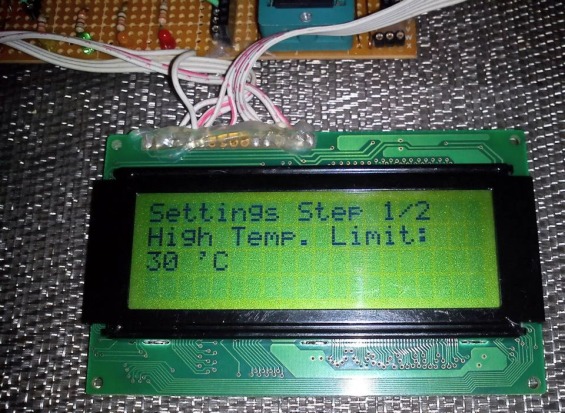
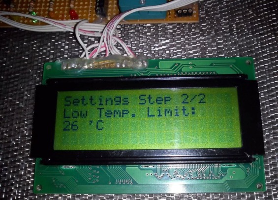
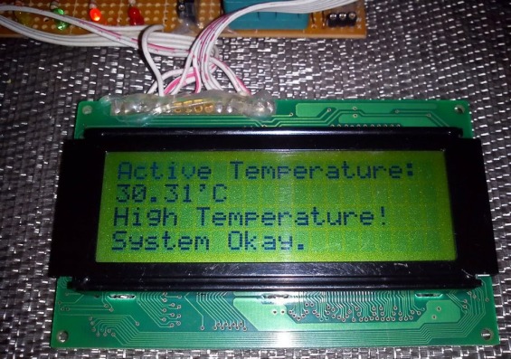
The system works as described here. Upon start-up the system sets up the required internal hardware of the AVR micro and then read the EEPROM memory. If the EEPROM locations contain garbage values then they are set with default values otherwise the previously stored values are read. After reading the EEPROM, the system starts to monitor temperature and waits for actions if any temperature limit is exceeded. The system at this point shows current temperature and system status. If the user wishes to set parameters then he/she has to press the setup button and enter the settings menu. In the settings menu there are three settings and these are high and low temperature limits (Figure 1, 2) and the number of passes the system will make prior to issuing a fault message. If, for example, the high temperature limit is set to 40˚C, the low temperature limit is set to 20˚C and the number of system passes is set to 45, and the current temperature gradually rises to 41˚C from 30˚C, the system will trip high temperature alarm and start the cooler. The LCD display will show high temperature alarm (Figure 3). Now if the temperature starts to decline and reach a value in between (40˚C – (40˚C -20˚C)/2) =30˚C [i.e t_delta] and 20˚C within the 45 system passes then the cooler is turned off and no fault message is generated. The system resumes to normal state. If the temperature didn’t decline to the range mentioned as above then it is assumed that the cooler is either faulty or some other thing is causing too much heat generation which is exceeding the cooler’s capacity. Thus a fault warning is issued for the cooler and it is shut down until the fault has been cleared. In this way both the hardware and the cooler is protected from damage. The same scenario happens during the low temperature alarm. If both the cooler and the heater fail then the system goes in a complete halt state until reset or given attention.
 |
|
| Figure 1. | Intelligent temperature monitoring and control system: setting the high temperature limit. |
 |
|
| Figure 2. | Intelligent temperature monitoring and control system: setting the low temperature limit. |
 |
|
| Figure 3. | Intelligent temperature monitoring and control system: display high temperature alarm |
Downloads
Source and HEX files - download