Dave Allen, Dash Inc, Kansas City, KS
A counter’s self-presetting feedback loop hunts for the center count
The simple circuit exhibits the basic characteristics of a traditional analog phase-locked loop but has no analog components other than the reference oscillator. Other digital PLLs exist, including those employing an up/down counter, but this one is simpler and more flexible.
The circuit initially found use more than 30 years ago as a clock regenerator in a data separator for a self-clocking code, such as Manchester or biphase, in magnetic recording. It quickly became clear that it has many other applications. The circuit also served as the basis of a servo controller for a tape drive’s capstan motor/tachometer. LSI disk/tape-controller chips incorporated both the data separator and the capstan servo controller, with the advantage of having no analog circuitry and no requirements for adjustment. Because it was used in the production of commercially available products so long ago, it is not patentable today and is free for use.
The example in Figure 1 uses only three ICs to make prototyping quick and the explanation simple. The connections between the 74161 counter outputs and the preset inputs form a rudimentary ROM implementing a look-up table (Table 1). The 16XREF should be a square wave or at least not a narrow pulse because you must take into account things that happen on both the leading and the trailing edges and setup times. The INPUT pulse must be long enough to meet the clock pulse-width requirements of the logic family you use for the 7474 D flip-flop.
 |
|
| Figure 1. | The counter loads its own data input to generate an output locked to the input signal. |
| Table 1. Mini mal counter preset |
|
Count
value |
Q3
|
Q2
|
Q1
|
Q0
|
D3
|
D2
|
D1
|
D0
|
Preset
value |
|
15
|
1
|
1
|
1
|
1
|
1
|
0
|
1
|
1
|
11
|
|
14
|
1
|
1
|
1
|
0
|
1
|
0
|
1
|
1
|
11
|
|
13
|
1
|
1
|
0
|
1
|
1
|
0
|
1
|
0
|
10
|
|
12
|
1
|
1
|
0
|
0
|
1
|
0
|
1
|
0
|
10
|
|
11
|
1
|
0
|
1
|
1
|
1
|
0
|
0
|
1
|
9
|
|
10
|
1
|
0
|
1
|
0
|
1
|
0
|
0
|
1
|
9
|
|
9
|
1
|
0
|
0
|
1
|
1
|
0
|
0
|
0
|
8
|
|
8
|
1
|
0
|
0
|
0
|
1
|
0
|
0
|
0
|
8
|
|
7
|
0
|
1
|
1
|
1
|
0
|
1
|
1
|
1
|
7
|
|
6
|
0
|
1
|
1
|
0
|
0
|
1
|
1
|
1
|
7
|
|
5
|
0
|
1
|
0
|
1
|
0
|
1
|
1
|
0
|
6
|
|
4
|
0
|
1
|
0
|
0
|
0
|
1
|
1
|
0
|
6
|
|
3
|
0
|
0
|
1
|
1
|
0
|
1
|
0
|
1
|
5
|
|
2
|
0
|
0
|
1
|
0
|
0
|
1
|
0
|
1
|
5
|
|
1
|
0
|
0
|
0
|
1
|
0
|
1
|
0
|
0
|
4
|
|
0
|
0
|
0
|
0
|
0
|
0
|
1
|
0
|
0
|
4
|
To test your prototype, make the INPUT approximately one-sixteenth of the 16XREF frequency and watch the output as you slowly vary the INPUT frequency. Use a signal generator that allows fine adjustment of the INPUT to measure lock range slightly above and below one-sixteenth of your XREF source. The dither is equal to the period of the 16XREF’s clock, but the output stays locked to the INPUT as you vary the INPUT ±20% or more. You can temporarily disconnect Pin 9 of the counter to see the output slipping past the INPUT when the frequencies are close to each other. Reconnecting Pin 9 demonstrates the locking action. The output is a square wave when the INPUT is exactly one-sixteenth of 16XREF but becomes rectangular as you go above or below the center frequency.
In operation, the counter counts continuously, but each rising edge of the INPUT signal causes a preset pulse at the counter. From Table 1’s count and preset values, you can deduce that, whenever the counter gets a preset pulse, the count moves closer to seven or eight. If it is already at seven or eight, it remains there. The servo-loop error signal is the difference, at the moment the preset signal arrives, between the counter’s current state and seven or eight. This simple example uses the count value to halve the error signal for the preset.
If the INPUT signal is exactly one sixteenth of the reference but starts up at 180° out of phase, then the first preset pulse might occur when the counter is at 15. So, the counter presets to 11 and resumes counting from there. At the next preset pulse, the counter is at 10 and presets to nine. The next preset pulse occurs at a count of eight and presets to eight. It next presets to seven; when the next preset pulse comes in while the counter is at six, it again presets to seven and is now synchronized. The preset pulses arrive just before the counter’s most-significant bit goes from 0 to 1, which is what the INPUT signal is also doing.
If the INPUT signal is a little slower than one-sixteenth of the reference, the preset pulses arrive after the counter has counted beyond eight – to 12, for example. It gets preset to 10. Because the INPUT signal is too slow, however, the counter again goes to 12 when the next preset pulse arrives. The circuit is still locked, but the MSB stretches to match the slower INPUT signal. The same process maintains lock for an INPUT signal that is faster than one-sixteenth of the reference, but the MSB signal’s period shrinks to maintain lock.
An out-of-lock condition occurs if the INPUT is so slow that the counter goes past 15 and wraps around to zero or beyond before the preset occurs. It’s likewise out of lock if the counter can’t even count to zero before the next preset pulse. The circuit can lock on multiples and submultiples of the 16X reference.
You can tailor the locking characteristics and reduce the dither by adding more counter bits and putting a ROM between the counter’s outputs and the preset’s inputs (figures 2 and 3). By using a PROM, you can, for instance, divide the error by three or by four, which increases the lock range. You can also use a PROM to subtract one or two from the error signal instead of dividing the error by two. This approach dramatically narrows the lock range. You can use additional PROM output lines – that are not presetting the counter – for other functions.
 |
|
| Figure 2. | Two counters and a PROM enhance the versatility of the lock function. |
Because the counter’s preset pulse occurs at the moment that the error signal is available, you can program some more bits in the PROM and latch the error condition for another application’s benefit, such as to indicate an unlocked state or to indicate the INPUT frequency as high, low, or centered relative to the reference. This scheme, with the motor controller, could indicate the motor’s load as light, moderate, or heavy. For other applications, you could program a second parallel PROM to generate a sine wave by feeding samples to a DAC or a quasi-sine wave for a power inverter.
As a capstan-motor servo controller, the tachometer is the INPUT to the PLL, and the motor speed locks to a crystal reference. One output bit from the PROM, tailored for the motor PWM (pulse-width-modulated) signal, enables the servo to better control the duty cycle. The MSB of the preset is 0, forcing the system to work in the lower half of the address space whenever it is locked. This approach frees up the top PROM output line, which becomes the motor-control signal.
Using an 8-bit counter and a 256×8-bit PROM provides lots of room and many options for optimizing the motor’s behavior under varying load conditions. The programming of the top PROM line determines where in the counter’s cycle the motor PWM signal turns on and off. If the load on the motor is heavy, it slows down, letting the counters count longer and slightly higher before the preset occurs. As the counters count higher, the motor bit stays on longer, increasing the duty cycle of the PWM signal to compensate for the heavy load. The center point of the servo is 63/64, keeping locked operation in the lower half of the address space. The upper half of the address space is therefore in use only during motor startup, so programming the PROM’s motor PWM bit “on” whenever the counter is that high provides extra starting torque.
 |
|
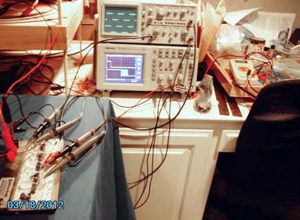
| Figure 3. | You can trigger from the input signal in the bottom scope’s top trace to see the dither on the locked output signal on the bottom scope’s bottom trace. |
By programming the PROM, you can control the lock range, or loop gain, to match the load variations; you can tailor the duty cycle to match the motor’s torque characteristics; and you can control the start-up torque.