Mike Rose
EDN
Using the fast dynamic load described in this Design Idea to test the transient response of a power system can reveal many critical operating characteristics. The voltage deviation resulting from a fast current step can provide insight into a regulator’s phase margin (Reference 2). Also, for power supplies that are located some distance from the point of load, transient testing can help determine the effective series interconnect inductance, shunt capacitance, and ESR. While the phase margin for commercial power supplies is typically verified by the supplier, adding remote sense can often destabilize the supply. The interconnect inductance and the load capacitance can introduce additional phase shift into the regulator control loop feedback, compromising stability. Many engineers have seen the tell-tale low frequency sine wave riding on the regulator output.
Performing transient testing on an assembled system allows a quick check on the system’s dynamic regulation stability and accuracy (Figure 1). Most commercial dynamic electronic loads have fairly slow current slew rates, which tend to limit their usefulness in testing faster regulator control loops, which can often reach steady state within 50 µs or less following a large load transient. A current slew rate of 10 A/µs or higher is needed for many high power systems.
 |
|
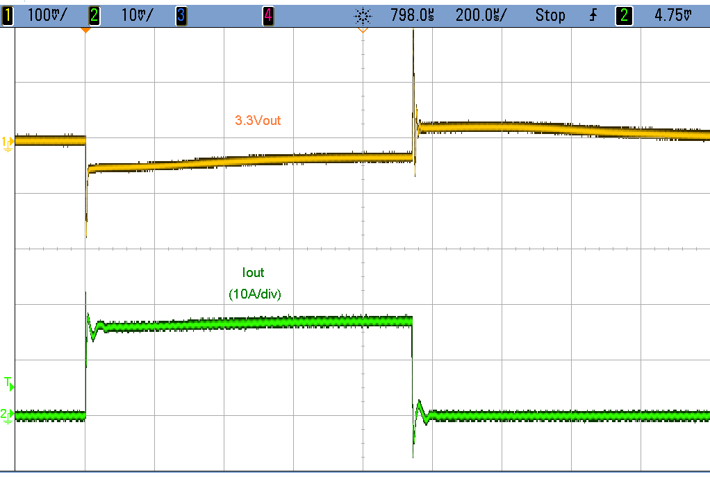
| Figure 1. | Application of a 50 W load transient to a commercial power supply exposes the response of the supply and the interconnect characteristics. From the response, approximate phase margin can be determined (Reference 2), along with regulator loop bandwidth and accuracy. |
Figure 2 is an adaptation of an application note (Reference 1) with a few notable improvements. The maximum power level has been increased to 150 W, and it has been designed specifically for 3.3 V, 5 V, and 12 V regulator outputs. R1-R3 form a resistive load switched by a single N-channel low-side MOSFET. The load resistors can be sized and populated to realize a large number of possible load combinations.
 |
|
| Figure 2. | Transient load tester schematic. |
At the core of the circuit, MOSFET driver U1 with a Schmitt trigger input is used to drive the MOSFET, and forms a relaxation oscillator with Q2, R8, R9, and C3. With the component values shown, the duty cycle is approximately 5% at a cycle time of 20 ms. Having a relatively low duty cycle permits a modest cooling solution.
R6 and R7 independently adjust the rise and fall times in combination with the MOSFET’s input capacitance, CISS. With the values shown, rise and fall time are approximately 1 µs. At this slew rate, the peak MOSFET gate current is around +110/-75 mA, which is well below the maximum rating of 1.4 A for U1. C2 can be added to further slow the edge rate. With a 1 µs rise/fall time and the relatively large gate resistors adding dissipative damping, MOSFET gate switching resonances will not be significant. R4 and C1 help dampen line resonances when the MOSFET switches off. The value of R4 is determined from the effective line inductance and the input capacitance. The value of 0.5 Ω has proved to be effective for typical wiring scenarios.
One of the more convenient features of this implementation is the two-wire connection to the DUT. For 3.3 V and 5 V systems, a 12 V boost converter is included to power the MOSFET driver and gate. No other connections or power sources are needed. The output of the boost converter can source approximately 350 mA with a 3.3 V input which may limit the amount of current that can be provided to charge the MOSFET’s gate. A low ESR aluminum capacitor, C5, supplies some of the initial gate charging current for faster current edge rates. For 12 V operation, a direct connect version can be assembled by replacing C7 with a 0 Ω resistor, disabling the boost converter. There will be some voltage drop across L1 and D2, but this will not affect proper operation of the circuit. D3 protects the boost converter circuits from reverse polarity (note that the body diode of Q1 will conduct during reverse polarity, likely leading to excessive dissipation in the MOSFET).
The entire circuit fits comfortably on a 3” × 5” two-layer PCB, including the heat sink and a small 12 V fan. With only two wires to connect, operation is very straightforward. The tester’s leads must be short and have low inductance to prevent ringing from the lead reactance. DUT connection should be made near the point of load or the remote sense location. The tester’s common and the voltage probe return leads should be connected at a single location. This location should also be selected to have a low impedance path back to the power source.
Pressing the momentary pushbutton PB1 starts the astable circuit and the dynamic load begins switching. If desired, quiescent PSU loading can be provided externally. R5 and J2 provide a convenient high bandwidth means for measuring the pulsing current. A straight 50 Ω coax can be connected directly to an oscilloscope input for monitoring current with a scale of 1 mV/A. The voltage measurement should also be made near the point of load or remote sense point and should be AC-coupled to a second scope input. The voltage probing must be done with care. Probe inductance from a distant ground/return lead will cause misleading measurements. A small series resistor (several ohms) at the probe tip can be added to dampen out the high frequency ringing from the probe’s ESL. Also, avoid probing right at the pads of a very low ESR decoupling capacitor which may filter or dampen the voltage response unrealistically.
References