The performance of solar-powered electronic devices may suffer in twilight conditions. In particular, microprocessors often used to perform solar power conditioning (such as in maximum-power-point trackers) do not like unstable power or smooth edges on power-up. The solar array supervisor described here helps with this problem by offering power supervision at the cost of only three transistors.
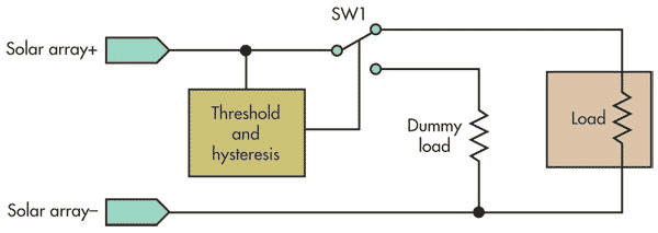
The circuit connects the microprocessor to the panel when the array can power it and disconnects it when the array cannot power it. Because an unloaded solar array supplies a high voltage even in poor lighting, the supervisor circuit employs a dummy load greater than the real load (Fig. 1). This allows the threshold and hysteresis block to make a proper measurement. When the array reaches the correct voltage threshold, the supervisor switches it to the real load.
 |
|
| Fig 1. | The solar array supervisor includes a dummy load greater than the real load to make a correct determination of when the array can power the load. |
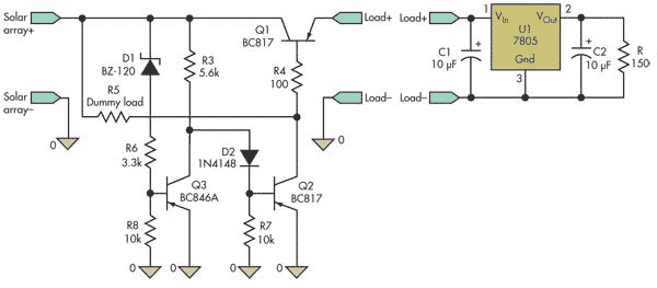
Zener diode D1 defines the threshold (Fig. 2). The difference between the real load and the dummy load, which must drain more current than the load, determines the hysteresis. The schematic shows an example of an expected load, a linear regulator (7805) used to power a microcontroller and loaded by a 150-Ω resistor.
 |
|
| Fig 2. | D1’s zener voltage and Q3’s Vbe determine the threshold for when the solar array can power the load successfully. The response in Figure 3 was obtained by using a 180-O dummy load. |
When the input from the solar array is below the threshold (D1’s zener voltage plus Q3’s Vbe), Q2 is on and the panel is loaded by the dummy load, R5. When the input exceeds the threshold, Q3 shuts off Q2, disconnecting the dummy load. This raises the voltage on Q1’s base, supplying power to the load. Because the load is lighter than the dummy load, the voltage on the solar array increases, as does the current on Q3’s base. Thus, the circuit acts like a trigger, confirming the reached condition.
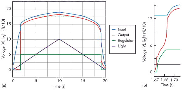
Figure 3a shows the circuit’s performance when connected to a small solar array (0.5 A shorted, 19 V open), while the light was varied from 0% to 100% and back to 0%. A 100-µF capacitor was placed at the input, and the output load was a 7805 with 10-µF capacitors at its input and output. The solar array supervisor delivered a 10-ms rising edge on 5 V at the regulator’s output (Fig. 3b).
 |
|
| Fig 3. | The circuit was tested with a typical load while the light on the solar array was varied from 0% to 100% and back to 0% (a). The expanded detail (b) shows that the supervisor provided a 10-ms rising edge on 5 V at the regulator’s output. |