Pete
Back Shed
This project demonstrates magnetic levitation. It's a fun and educational project.
Magnet Levitation
I seen a gadget that had a magnet levitating in mid air, and started to wonder how it was done, so decided to test a few theory’s.
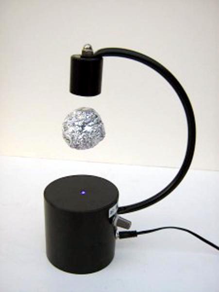
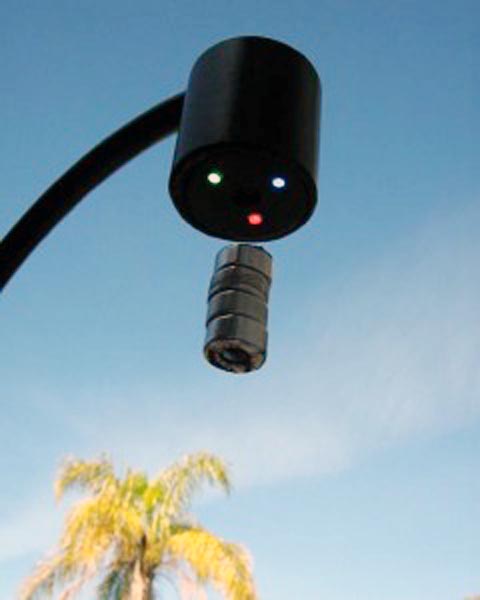
After a little trial and a few errors, I managed to get one to work (Figure 1).
|
||||
| Figure 1. | Magnetic levitation in action. | |||
The basic principle is a coil to create a magnet field and a linear hall sensor on the face of the coil, to detect the field of the permanent magnet as it approaches, then turn the coil off, as the magnet falls way from the coil, this then triggers the coil to switch back on again, effectively keeping the magnet in levitation.
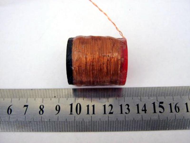
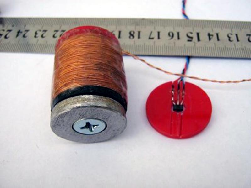
I wound a small coil with 0.45 mm enamel copper wire (Figure 2), over all size and number of turns is not over important, but the resistance needs to be high enough to not exceed the power supply current limit. I wanted to stay below 0.5 amp with a 5 volt supply (5 / 0.5 = 10 ohms) and targeted 10 to 15 ohm coil.
 |
|
| Figure 2. | Electromagnetic coil. |
As the circuit has now developed to turn the coil off in the absence of a magnet, the coil resistance could be reduced to 5 ohms or above.
The device works in the small area of distance where the magnet is just not able to have enough pull to attach itself to the metal and needs the little help from the coil to pull it up, the coil on its own is not strong enough and the metal plate is needed in conjunction with the coil.
I cut out a solid 5 mm metal disc to match the coil diameter, but full diameter of the coil is not needed (Figure 3).
 |
|
| Figure 3. | A metal plate needs to be attached to the bottom of the coil. |
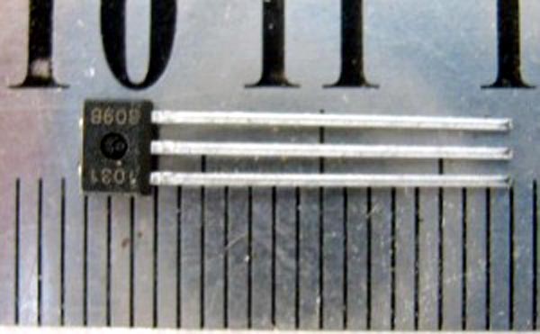
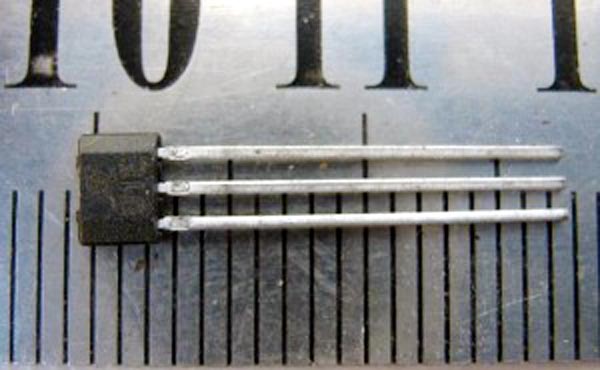
The hall sensor is attached to the metal plate, the flat side of the hall sensor faces towards the coil (Figures 4, 5).
 |
|
| Figure 4. | This side to face the coil. |
 |
|
| Figure 5. | This side to face the magnet. |
For ease of fitting I mounted the sensor in a plastic disc I cut from some acrylic sheet, but tape or glue will work (Figure 6).
 |
|
| Figure 6. | The side of the sensor with the rounded corners faces the magnet. |
It is important to mount the sensor close to centre of the coil/metal plate.
Originally I tried to use a Picaxe to read the hall sensor and do the switching of the coil via a transistor, but the picaxe was too slow. I then went to using a LM358 Opamp with good results.
The Opamp circuit is very basic and simple. What I noticed was when the magnet is levitating the circuit only draws about 50-150 mA, depending on the object weight, but when the magnet is removed or is knocked out of levitation, the coil is switched hard full on. This causes the 5 volt regulator to run very hot or overheat.
The circuit has now been redesigned to use the second half of the dual opamp to switch the coil off in the absence of the magnet (Figure 7).
 |
|
| Figure 7. | Electric circuit device. |
The whole circuit including the coil operates off 5 volts, and a LM7805 voltage regulator is used to supply this, so the maximum current needs to be kept below about 0.5 amps.
The linear hall sensor (UGN3503U) has a nominal output of around ½ the supply voltage. When a magnet is brought near the sensor the output voltage increases or decreases depending of which pole of the magnet is used (north or south pole), for this circuit it is set to increase in voltage as the magnet south pole approaches the sensor.
The sensor output is connected to the inverting input of the opamp (opamp-1), and the non inverting input of opamp-1 is connected to a pot set as a voltage divider, the pot is used to trim in the balance point of levitation for different size magnets or object weights attached to the magnet.
Opamp-1 output is connected to base pin of a BD681 transistor via a 1K resistor, the BD681 is used to do the coil switching, almost any NPN transistor or MOSFET could be used that has a 1 amp or greater rating.
The second half of the opamp (opamp-2) is used to monitor the output frequency to the transistor, this is done by a 100K resistor off opamp-1 output into a 1 µF cap, effectively creating a analogue voltage which supplies the non inverting input of opamp-2.
Opamp-2 inverting input is supplied with a voltage from a trimpot set as a voltage divider. When the coil is being pulsed to keep a magnet in levitation the analogue voltage on the non inverting input is lower then the setting on the inverting input, but when the magnet is removed the voltage increases as the coil is switched full on with no pulsing. This pulls the non inverting input higher than the set voltage on the inverting input and switches the output high. The output of opamp-2 is connected to the base pin of a BC337 NPN transistor via a 1K resistor. The BC337 has the collector connected to the base pin of the BD681 and effectively shorts out the 1K resistor on the base of BD681 to ground switching off the coil.
A second BC337 transistor is also connected to the opamp-2 output that controls the leds by shorting out the limiting resistor to the leds to switch them off.
To set the coil switch off point it is as simple as a 1 time adjustment to the trimpot till the led just turns off. When a magnet is brought in range of the sensor the led will turn back on and the coil will start to be pulsed, then its just a matter of adjusting the pot till a balance point is found for the magnet.
This is really a fun project to build and will fascinate many people of how it works with an object levitating in mid air.
Now the circuit bugs have been worked out it is a very simple circuit to construct with only a few basic components.
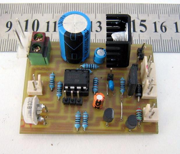 |
|
| Figure 8. | View of the circuit Board from the elements. |
And now for the PCB (Figures 8 and 9)...
 |
|
| Figure 9. | The printed circuit Board pattern from the side of the tracks. |
Note: the points marked “TP” were Test Points where I had header pins for the Cro to attach to during development, and can be disregarded in the final circuit.
A few tip and notes
The coil wires needs to be connected the right way around or the coil will produce the incorrect magnetic pole for the circuit. This will be a trial and error to work this out, so if the circuit don’t work to start with than swap the coil wires around.
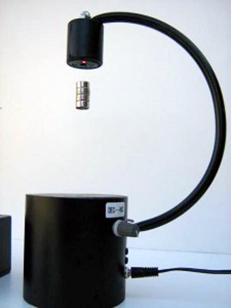
The magnet size is not overly important but it do need to be a reasonable strength magnet and the small Neo (rare earth) magnets work best.
A heat sink will need to be fitted to the voltage regulator as it will run quite hot. Also keep the power supply voltage as low as possible, from 7 to 12 volts as the higher the input voltage the greater the temperature generated by the 5 volt reg to lower the voltage.
The hall sensor has a maximum input voltage of 6 volts and is why the circuit is operated by a 5 volt supply.
If you find the magnet gets the jitters and falls out of levitation, this can be caused by several reasons, the main one is the metal plate is not thick enough and try adding a few more washers.
OR.. the sensor is not mounted near the centre of the coil.
OR..the setting on the pot is too high and needs to be decreased to lower the magnet away from the coil a little. (this is a fine adjustment)
OR.. the coil is mounted crooked and is not close to vertical.
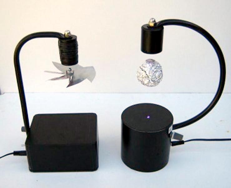
Adding flashing RGB leds above and below the magnet creates a nice effect if a shiny object like a ball of alfoil is levitated (Figures 10 and 11. It is best to file the top of the led off to give a broader light for the top led, as it is close to the object.
 |
|
| Figure 10. | Adding flashing RGB leds creates a nice effect. |
 |
|
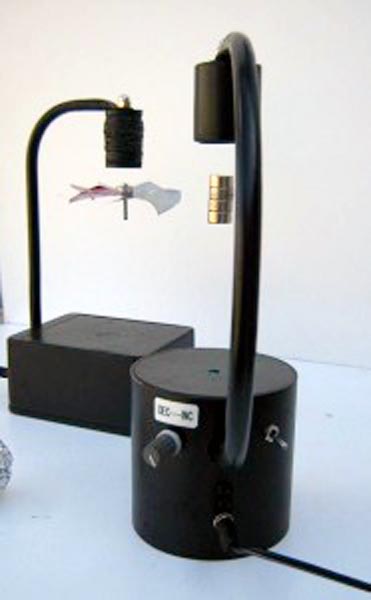
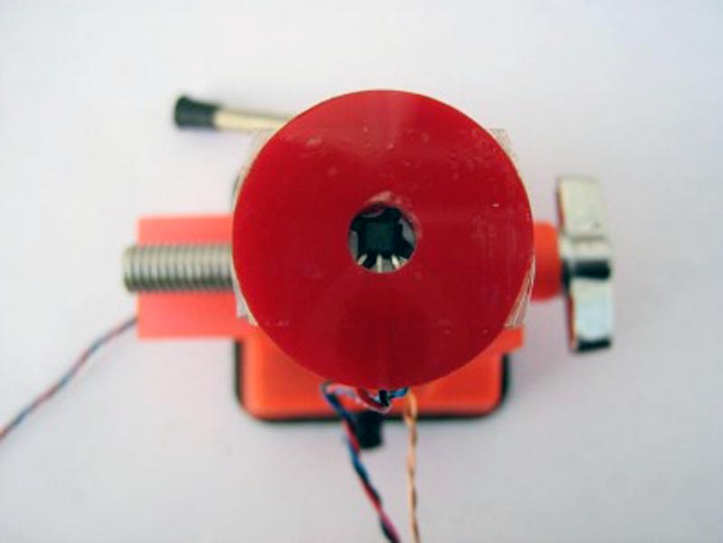
| Figure 11. | A different effect is to make a small windmill fan and attach the magnet to the centre. |
A different effect is to make a small windmill fan and attach the magnet to the centre. I used a coke can cut up for the material to make the fan. Then place a small “Tea candle” or scented oil burner under it and the rising warm air will make the fan spin in levitation. It takes very little heat to spin the fan, to the point in a cold air room once the coil has warmed up the thermal conduction passed the coil will spin the fan slowly,(if the surrounding air is warm this will not work)
A coil salvaged from a solenoid should work, ok but just watch the power consumption of the coil so not to overload the circuit, as many solenoid coils are very power hungry.