Part 1 - Hardware: Schematic, PCB and case.
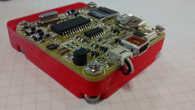
Hi all! I’m continuing here with the last board I design and now I’m continuing testing. It’s a battery-powered small datalogger based on a PIC18F2620 microcontroller (Figure 1). The idea comes a few months ago, talking with a friend. He needs something to monitoring temperature and humidity inside a sea container, for a three weeks travel from Spain to China. Low consumption is important, in order to have maximum autonomy with a small battery. I use a HDC1050 temperature and humidity sensor, and a TEMT6000X01 ambient light sensor. The collected data is stored on a micro SD card. Also the board has a RTC for timestamp, a Li-Ion battery charger, user pushbuttons and leds, and a MCP2221 USB bridge to communicate with the board and configure some parameters through software. Let’s see the board in detail!
 |
|
| Figure 1. | Portable temperature, humidity and light ambient datalogger. |
Hardware
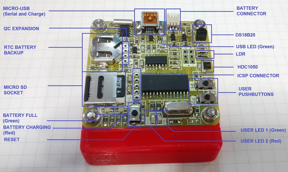
First of all, here’s a view of the board with the main components (Figure 2). After I’ll talk about the case. I also let in the board the footprint for a DS18B20 temperature sensor. Originally, it’s on the board because I’m not sure if I’ll be able to solder the HDC1050 sensor, so if I can’t, at least I can obtain the temperature from this sensor.
 |
|
| Figure 2. | Datalogger PCB with istalled components. |
The full schematic of the board is available in download section. It’s divided in the following parts:
Main diagram
Includes the mini-B USB connector, TVS diode for protecting the USB line and the rest of the connections.
Power supply stage
The board can be powered using a 3.7 V Li-Ion battery or through USB port (Figure 3). I use a 3.7 V/1100 mAh battery for this first prototype (LP603450). USB port is also used to charge the battery. I use the MCP73832-2ACI/OT regulator from Microchip with a Rset of 4K7 (not 10K as appear in the schematic). This allows a current charge of around 220 mA/h. D4 (red) and D5 (green) leds indicate the status of the charge. Also, D1 (green) lights when USB power is present.
 |
|
| Figure 3. | Datalogger schematic: Power supply stage. |
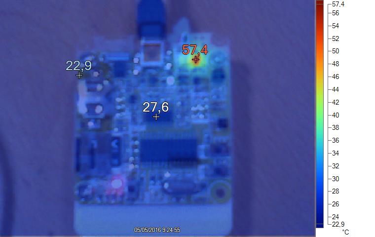
The hot point is the battery manager, when charging the battery. Although is a high temperature, is not critic and with this setup, the battery is fully charged in around 5 hours (Figure 4).
 |
|
| Figure 4. | Datalogger PCB temperature when charging the battery. |
System voltage is 3.0 V, so I use a TPS76930DBVR LDO regulator. with a maximum output current of 100 mA and a typical dropout voltage of 115 mV at 100 mA output. Also, there’s another LDO regulator, U10. This one is used to power the USB – serial converter. The input of this regulator comes from the USB port, so when there’s no connection with the USB, the regulator and also the USB converter are not powered, increasing the battery life.
Battery voltage is measured with the RA3 analog input of the microcontroller. I just set a voltage divider to adjust the maximum battery value (4.2 V at the end of the charge) to the 3.0 V maximum voltage on the PIC pins.
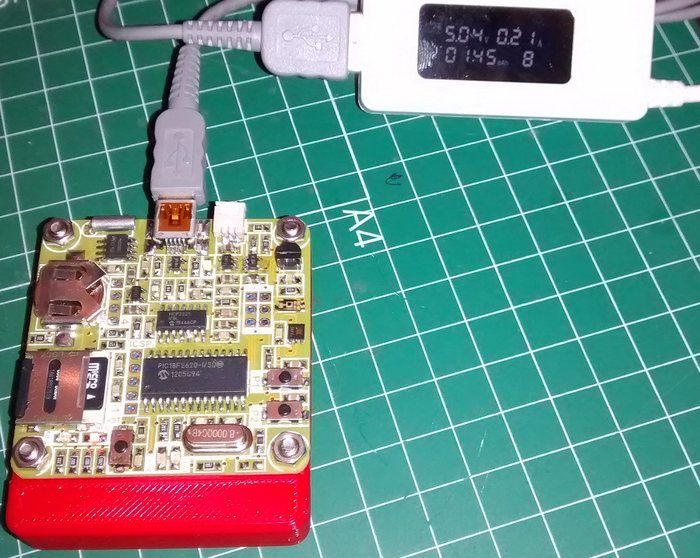
At this time, duration of the battery is around 10 days. With the actual software, there isn’t any low power implemented yet. The consumption is around 5-6 mA, including the DS18B20 sensor that I don’t use. I think that unassembly this sensor and forces SW to low power consumption, the goal of three weeks of autonomy is easy to reach.
 |
|
| Figure 5. | Datalogger: Power consumption when charging the battery. |
PIC18F2620 microcontroller
The brain of the board! 64KB Flash, 3968 RAM bytes, 1KB EEPROM, 25I/O, I2C, UART,…all condensed on a 28-pin soic package. Enough for this project! Of course, the board has the ICSP connector and also J4 and J5 connectors with accesible VCC, GND and three not used pins (Figure 6).
 |
|
| Figure 6. | Datalogger schematic: PIC18F2620 microcontroller, DS18B20 and ICSP. |
I2C bus
On the 3.0 V I2C bus are the HDC1050 temperature and humidity sensor and also the M41T00SM6 RTC (Figure 7). The RTC has a CR1220 battery for backup date and time. Also there’s a connector available with these signals for future uses. The I2C bus is implemented by software, because the I2C lines are shared with the SPI port, and I need it for the micro-SD card.
 |
|
| Figure 7. | Datalogger schematic: HDC1050 temperature and humidity sensor and also the M41T00SM6 RTC. |
LDR
A TEMT6000X01 ambient light sensor. It reads with the analog RA0 input (Figure 8). Because the internal ADC of the PIC has 10-bit resolution, maximum value will be 1023 that corresponds with maximum level of illumination.
 |
|
| Figure 8. | Datalogger schematic: Ambient Light Sensor TEMT6000X01. |
USB-Serial bridge
Based on the MCP2221 chip [1] that I use before (Figure 9).
 |
|
| Figure 9. | Datalogger schematic: MCP2221 USB-Serial bridge. |
Micro-SD Socket
I use this one from Molex because is easy to solder by hand. Not much to say here, just and SD card connected to the SPI port (Figure 10). You can check here the SD card specs [2].
 |
|
| Figure 10. | Datalogger schematic: microSD card SPI interface. |
User interface
Two pushbuttons (active low) and two led’s (D2 Green / D3 Red) for what user wants!
PCB and Case
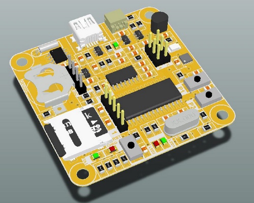
I design the board with components only on top layer, it’s easy to assemble. I use the DP5050 sick of beige PCB format from DangerousPrototypes. The gerber files of the board available on download section. And here’re a couple of 3D-previews images from Altium (Figure 11).
 |
|
| Figure 11. | 3D-previews images from Altium for Datalogger PCB. |
I order the boards to DirtyPCB company, and like always, the quality is excelent for the price. The one con I notice this time is that yellow board with white silkscreen is not easy to read, but I never make a yellow board.
Editor note:
To view the GERBER-files you can turn to online tools EasyEDA Gerber Viewer (Figure 12). In addition, there you can order the production of PCB.
 |
|
| Figure 12. | Datalogger PCB in EasyEDA Gerber Viewer. |
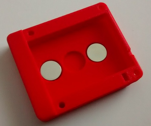
For first time, I make a 3D case for the board. To make this job, one of my best friend helps me in this design. He has his own company and has a lot of experience designing cases for electronic equipments. I send him the step model of the board and he designs the case, to fit the board and also the battery. The board fits perfect, but you can show the battery. Also, I need a small space to take out the wires from battery, and also add a method to fix the datalogger. We implement all this changes on the second version (Figure 13). I use two Neodymium Magnets to fix the board to any metallic surface. It’s a transparent method of fixing and the final result looks great. The .stl project file of this last case is available in download section.
 |
|
| Figure 13. | 3D case for the datalogger boar. Using two Neodymium Magnets to fix the board to any metallic surface. |
Downloads
- Datalogger Schematic (PDF) - download
- Datalogger GERBER-files - download
- .stl project files for case - download
References