Carl Pugh
EDN
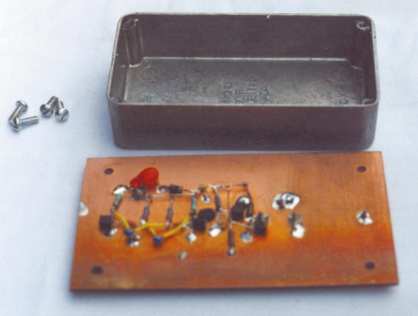
Most circuits use bypass capacitors and can deliver substandard performance if the capacitors have poor pulse characteristics. Few if any articles cover how to test bypass capacitors for pulse characteristics. The circuit in Figure 1 tests these characteristics. It charges the capacitor under test through 100 kΩ for approximately 1 msec and then discharges it through 10 Ω for approximately 40 nsec. The cycle then repeats. The circuit uses a double-sided copper-clad pc board. All the components except the 10 Ω resistor connect to one side of the board, so they can benefit from shielding by the cast-aluminum enclosure (Figure 2). All leads are as short as possible and as close as possible to the copper-clad board. The layout is such that you don't need the oscilloscope probe's ground lead; the ground on the probe contacts a ground post on the pc board. The ground posts, feedthroughs, connections to the capacitor under test, and oscilloscope probes use vector-board terminals.
 |
|
| Figure 1. | Test the pulse characteristics of bypass capacitors using this simple circuit. |
The circuit comprises an astable multivibrator using two 2N3904 transistors, Q1 and Q2, and associated components. A voltage reducer/shaper uses a trimmer capacitor, C1; a 100-pF capacitor, C2; and a 200 Ω resistor, R1. An amplifier uses a 2N3906 transistor, Q3, and associated components, and a power amplifier uses a PN2222A transistor, Q4, and associated components. C1, C2, and R1 produce a fast rise- and fall-time, 0.7 V pulse when the multivibrator's output switches negative. Because the Q3 transistor has no bias, it conducts only at the peak of the input pulse and produces a pulse with fast rise and fall times. The output from the Q3 drives Q4, causing that transistor to conduct for approximately 40 nsec. You can obtain interesting results when testing capacitors with long leads and then testing the same capacitors with short leads, corroborating the universal advice to keep leads short.
 |
|
| Figure 2. | Components all connect to one side of the pc board, and a cast-aluminum cover provides shielding. |