General information
Schematic diagram
Printed Circuit Board (PCB)
Arduino Sketch Highlights
Conclusion
Downloads
References
General information
The second version of the controller is made on a popular Wi-Fi module such as NodeMCU, which is based on the powerful Espressif ESP8266 system-on-chip (SoC). Such a solution will allow us to implement in our light controller additional functions inherent in the devices of the Internet of things (Figure 10). At this moment, there are many varieties of these Wi-Fi modules, which have different form factor, the number of general purpose I/O lines, the presence of an interface for debugging and programming. This diversity is due to the high popularity of Wi-Fi modules among radio amateurs and designers, as well as full support for the ESP8266 core in the Arduino integrated development environment. In other words, it is a miniature Arduino board with a Wi-Fi interface, with which you can create Internet devices of things (IoT) with enough rich functionality.
 |
|
| Figure 10. | Kitchen working area accent lighting with automatic control on NodeMCU support IoT functions. |
Next, we will look in detail at construction and the operation principle of this version of the controller.
The idea to implement the IoT function in the additional light controller was born after I evaluated the possibilities of the cloud service and mobile application myDevices Cayenne for developing IoT devices on Raspberry Pi and Arduino [1, 2]. I recommend that you familiarize yourself with the reviews published on our portal in order to understand the principle of building and operating the system.
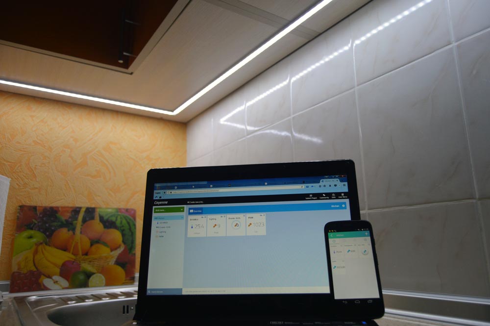
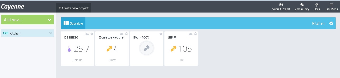
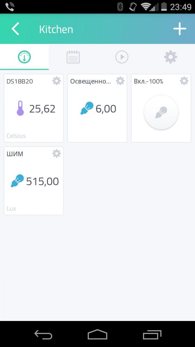
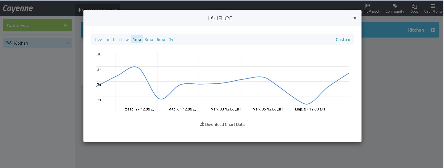
Now, considering that the device for automatic light control supports the Internet connection (in particular, to the Cayenne server), we can implement additional useful remote control and management functions. At the moment on the Cayenne dashboard I can observe the level of illumination and its change, the current PWM mode of controller, the temperature in the room, and also I can switch the controller to manual mode from the application on the smartphone and turn the additional light to maximum brightness (Figure 11). All data arriving at the Cayenne server is saved, and in the future I can view detail data (and download) and statistics of changing data for different time periods, and also set up notification conditions for a mobile phone or e-mail (Figure 12). Thus, this controller, in addition to controlling the lighting of the working area in the kitchen, can perform additional automation functions and it can be called a remote sensor (sensor node).
 |
|
| a) | |
 |
|
| b) | |
| Figure 11. | Cayenne dashboard for automatic lighting controller in kitchen: a) in the browser; b) in the mobile application. |
 |
|
| Figure 12. | One of the options for details display (statistics) of temperature changes in the kitchen. |
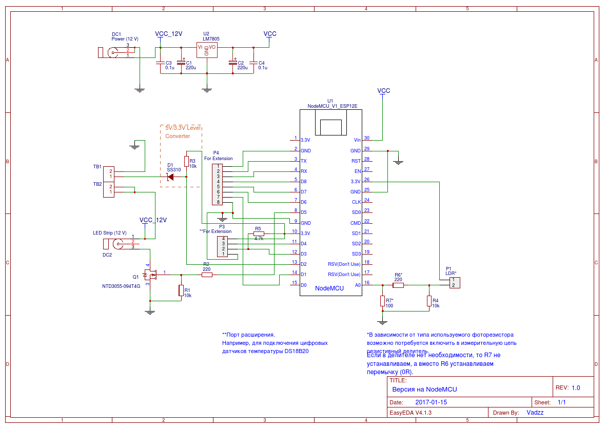
Schematic diagram
The schematic diagram in pdf format is available for download in the download section, the original project is available online in the EasyEDA.
As I noted in the first part of the article, the circuitry of the device on NodeMCU differs somewhat from the similar device on Arduino (Figure 13). Firstly, this is due to the fact that the nominal supply voltage of the ESP8266 SoC is 3.3 V. Secondly, the technical documentation for SoC, practical manuals and thematic forums do not give an unambiguous answer to the question of the compatibility of Wi-Fi modules on the ESP8266 with 5 V devices.
In addition, in NodeMCU modules, a 3.3 V line voltage regulator (usually from the AMS1117-3.3 series) is installed for powering the SoC, for which the maximum input voltage is 15 V (in some versions up to 18 V). In this case, the NodeMCU module could be powered directly from the 12 V power supply. However, for some obvious reasons, I decided to install an additional 5 V voltage regulator with the appropriate filter capacitors. The 5 V supply voltage from 5 V regulator output is fed to the Vin input of the Wi-Fi module.
 |
|
| Figure 13. | Schematic diagram of the Controller (NodeMCU Version). |
The PWM circuit of the LED tape control did not change. The power MOSFET Gate pin is connected to the D5 NodeMCU port.
The input voltage range of the A / D converter integrated in the ESP8266 is 0 - 1 V, therefore the connection circuit of the light sensor (photoresistor) is slightly changed. Depending on the type of photoresistor used, it may be necessary to include an additional resistive divider in the measuring circuit. In my case (a photoconductor VT93N1 with a rating of 12 kOhm) there is no need for a voltage divider - even under high brightness conditions the voltage at the input of the ADC did not reach 0.9 V, so the resistor R7 is not installed, and instead of R6 a jumper (SMD resistor 0 Ω) is placed.
The DS18B20 temperature sensor is connected to the P3 connector. The 3.3 V supply voltage for the temperature sensor is supplied from the NodeMCU module, the sensor signal terminal with the pull-up resistor R5 is connected to port D3.
Connector P4 and pin 3 of connector P3 are provided for the possibility of further expansion of the functional.
To connect the motion sensor using a similar dual connector TB1-TB2. The output line of the motion sensor is connected to the D2 port via the logic level matching circuit (5 V / 3.3 V) made on the resistor R3 and the Schottky diode D1. With the current method of connecting the motion sensor (as in the case of the Arduino controller), the logic level matching scheme is not needed, and it can be eliminated. However, depending on the type of motion sensor used and the way it is connected, this circuit may be mandatory, since the ESP8266 can be damaged by operation with 5 V signals.
I note that the applied logic level matching scheme is one-sided. It is desirable to use Schottky diodes in the circuit - they have a low direct voltage drop.
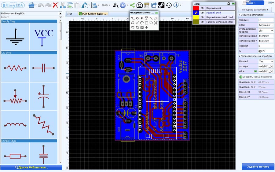
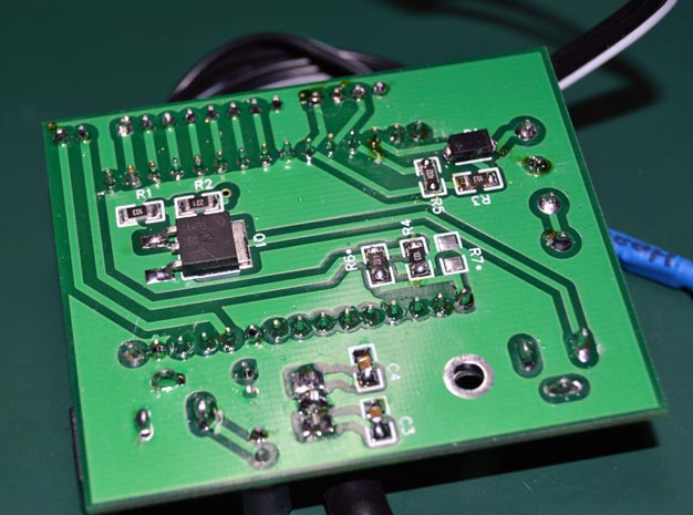
Printed Circuit Board (PCB)
The design of the double-sided printed circuit board is developed in EasyEDA; Gerber files are available for download (Figure 14). The components and connectors tried to arrange the same way as on the Arduino Version, however, the board size was slightly larger. You can also view the project Gerber files using GerberViewer.
 |
|
| Figure 14. | PCB for Controller on NodeMCU designed in EasyEDA. |
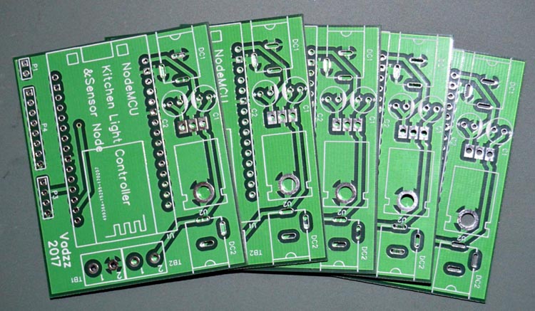
The top and bottom layers are filled with Copper Area (GND, ground) and silkscreen. As with the Arduino board, the minimum order (5 pcs.) for PCB manufacturing was made as soon as possible, but in the end I received 6 PCBs.
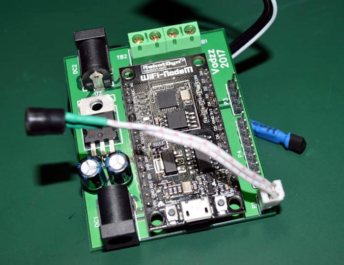
All components are installed freely, and I did not even check the sizes and diameters of the holes in the library components used. The resulting set of printed circuit boards is shown in Figure 15. The board with installed components is shown in Figure 16.
 |
|
| Figure 15. | Printed circuit boards ordered and manufactured in EasyEDA. |
 |
|
 |
|
| Figure 16. | View of the controller board on the NodeMCU with the installed components. |
Arduino Sketch Highlights
The source code of the microcontroller program (sketch) is simple in understanding and provided with comments. The sketch is provided "as is", I do not exclude the possibility of further optimization or adding new functions and operating modes of the controller. Here everything depends on your imagination and desire.
The main functions in the sketch and modes of operation for controller on NodeMCU remained the same as in the version on Arduino.
Pay attention to the definition of the I/O ports, additional libraries for working with the temperature sensor and the Cayenne server, constants for connecting the NodeMCU over Wi-Fi to the home network. In addition, I note that on ESP8266 in Arduino IDE with the analogWrite () function implemented software PWM with a range of 0-1023 (default). Consequently, the delays in the cycles of a smooth change in brightness during the transition from one operating mode to another have changed. In the PWM control loops, the delay () function is used, and at the end of the main program loop the yield () function is applied - this is necessary so that the ESP8266 processor, in addition to the user application, can perform background tasks to maintain the Wi-Fi connection. For connect the controller to the Cayenne server, you must specify in the source code a unique authorization key for the device that you will receive at the initial stage of adding a new device to the Cayenne dashboard. To find out how to do this, I recommend that you read the articles about myDevices Cayenne published on Radiolocman.com.
With current firmware version controller in automatic mode controls the brightness of the additional lighting in the kitchen and sends data (current illumination level, temperature and PWM value) to the Cayenne server, and also receives data from the Cayenne server about the current status of one button on the dashboard for Manual forced lighting on the maximum brightness. Pressing this button (on the dashboard or in the mobile application, called "Enable-100%") disables controller automatic mode for 2 hours and turns additional light on for maximum brightness. At the end of this period, the controller switches back to automatic operation mode and switches to the inactive state button on the Cayenne dashboard. By the way, I learned about the possibility to change the state of the button on the dashboard from a remote device during experiments; In the Cayenne help section information about this function I did not find.
Virtual channels are used to communicating with the Cayenne server (Listing 3).
Listing 3. Defining virtual ports for data exchange with the Cayenne server.
#define VIRTUAL_PIN_0 V0   // Virtual PIN 0: LDR
#define VIRTUAL_PIN_1 V1   // Virtual PIN 1: Current PWM Value
#define VIRTUAL_PIN_2 V2   // Virtual PIN 2: "Enable-100%" Button state
#define VIRTUAL_PIN_3 V3   // Virtual PIN 3: DS18B20 temperature sensor
Virtual PIN V2 is used to control the state of the button «Enable-100%» on the dashboard. The controller on this channel sends a value (1 or 0) to change state of the button (Listing 4). The server, receiving a value on virtual channel V2 equal to 0, deactivates the button on the Cayenne dashboard and changes the icon on it.
Listing 4. Changing the state of the button on the Cayenne dashboard from a remote device.
if ((Cayenne_Button == 1) && (millis() - timeout_3 > interval_4))
{
//manual mode, 2 hour timer interval expired
    Cayenne_Button = 0;
    Cayenne.virtualWrite(V2, Cayenne_Button);  // button deactivation (write 0)
    timeout_3 = millis();                      // reset timer
    mode=3;                                    // return to automatic mode
}
The processing of the Cayenne dashboard button pressing event is performed by the function CAYENNE_IN (V2) (Listing 5).
Listing 5. Cayenne dashboard Button processing.
CAYENNE_IN(V2)
{
  Cayenne_Button = getValue.asInt();
  if (Cayenne_Button == 1) {
    mode=2;
    Mode_Set();
  }
  else {
    mode=3;
    Mode_Set();
  }
}
Temperature, illumination and the current PWM (controller operating mode) value sending to Cayenne is performed by separate functions of the form CAYENNE_OUT (). These are very simple functions, the construction of which was discussed in detail in [3]. Sending and updating of data occurs automatically on request from the Cayenne server, but it is possible to implement your own algorithm and change the frequency of updating the data.
Conclusion
The presented two options for automatic control of additional LED lighting in the kitchen are simple enough, but, in my opinion, functional and practical. At this moment I have a controller on the NodeMCU working in the kitchen. In the future, I plan to connect additional sensors and a ventilation control scheme in the kitchen to the system.
Of course, both devices are not ideal, and may require optimization or modification. For example, the controller on the NodeMCU with Cayenne has several nuances related to the features of the Cayenne software libraries for Arduino. When power is applied to the controller, the execution of the main cycle of the user program will start only after the wireless connection with the access point has been established. If the wireless network disconnects or the connection to the Cayenne fails, the controller will continue to perform its main function (lighting control), but there will be delays when processing events from the motion sensor, when changing from one operating mode to another. All of this can be solved, but for all the time of this controller is working this situation has not happened ...
I want to note that the controller on Arduino can also integrate the IoT functions and connect it to the Cayenne server using a wired connection (RS232, RS485) or using wireless transceiver modules on the NRF24L01 chip. In the latter case, you will have to take care of choosing the optimal remote devices network topology and developing a master device that will collect and process data from the slaves in the network.
Downloads
References
- Cayenne - Simplifying the Creation of IoT
- Cayenne dashboard simplifies IoT project building on Raspberry Pi
- Free, cloud-based EDA application for drawing circuits, running SPICE simulations, designing PCBs, and even placing orders for fabricating PCBs - EasyEDA
- Project files for controller on NodeMCU in EasyEDA
- Platform to create IoT projects on the Raspberry Pi and Arduino