John Ambrose
EDN
Tracking notch filters find use in harmonic-distortion analyzers; they also can remove heterodyne noise from ham-radio systems. A conventional tracking switched-capacitor notch filter relies on a bandpass filter, a voltage-to-frequency converter, and a notch filter to track the incoming signal and remove undesired tones. The bandpass filter in these circuits sometimes adjusts to the wrong frequency, meaning that the undesired tone would have no attenuation.
The circuit in this Design Idea uses IC1, a 74HC4046 PLL (phase-locked-loop) IC, which operates as fast as 1 MHz, to improve the noise immunity of the system (Figure 1). IC2, an RDD104 IC from LSI Computer Systems Inc, provides a 1000-to-1 divider in an eight-pin package. IC3, Mixed Signal Integration’s MSHN5 1000-to-1 clock-to-corner switched-capacitor highpass/notch filter, comes in an eight-pin package.
 |
||
| Figure 1. | This audio notch-filter circuit uses a PLL to improve noise immunity. | |
You feed IC1’s VCO (voltage-controlled oscillator) output into the clock input of IC2. IC2 can perform 10-, 100-, 1000-, and 10,000-to-1 divisions using the DIV1 and DIV2 pins. You tie the output of RDD104 to the COIN of IC1. By using IC1’s EX/OR phase comparator, you can improve noise immunity. You apply the input signal to both IC1 and the input of IC3, whose clock you derive from the CLKOUT pin of IC2.
 |
||
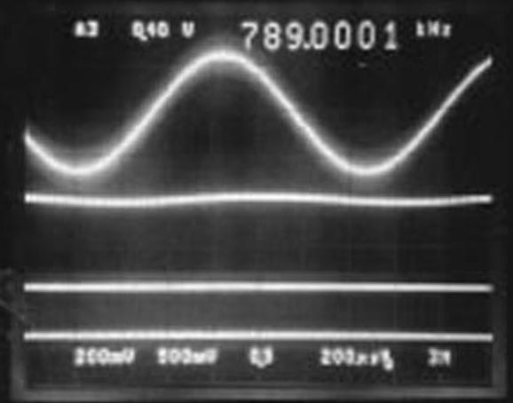
| Figure 2. | You feed the circuit an input tone (top trace) and get the output signal from the MSHN5 (second trace). The third and fourth traces represent the clock signal from the 74HC4046 PLL. |
|
The MSHN5, IC3, contains both selectable highpass filters and selectable notch filters. When you tie the FSEL pin high, it selects notch; tying TYPE to AGND selects the narrow notch filter. This step ensures the removal of only one tone from the input signal with little information loss. IC3’s 1000-to-1 clock-to-corner ratio reduces the chance that aliasing signals will affect the output. For voice applications, for example, no signals of 500 kHz or higher would be available to alias into the passband. A sample setup uses an input frequency of 789.13 Hz at a clock frequency of 789.13 kHz, 1000 times the input signal (Figure 2). The PLL tracks the input, moving the notch filter to 1.24 kHz.