S. Chekcheyev
EDN
The voltage amplifier in Figure 1 exhibits smaller nonlinear distortion than does the conventional amplifier in Figure 2.
 |
||
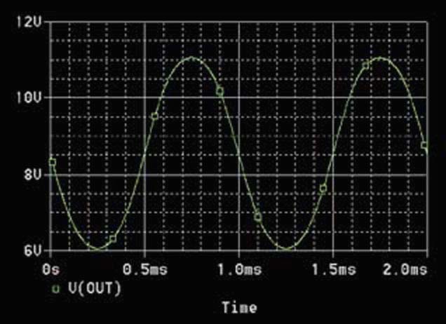
| Figure 1. | The addition of a simple diode in the emitter circuit yields the symmetric waveform in Figure 4. |
|
 |
||
| Figure 2. | This amplifier circuit produces the distorted waveform in Figure 3. |
|
Diode D1 compensates for the distortion inherent in the n-p-n transistor. The voltage gain of a common-emitter amplifier depends on the transconductance of the transistor. The transconductance of the bipolar transistor is as follows:
where e is the charge of an electron, k is Boltzmann's constant (approximately 1.38×10⁻²³J/°K), T°C is temperature in degrees Celsius, I is the emitter current, and n=e/[k(273+T°C)]. So, the transconductance is proportional to the emitter current. Consequently, the instantaneous voltage-gain coefficient of the conventional common-emitter amplifier is proportional to the instantaneous emitter current. As a result, the negative half-cycle of the output signal gets more amplification than does the positive half-cycle (Figure 3).
 |
||
| Figure 3. | Nonlinearity of the transconductance of Q1 results in this distorted waveform. |
|
 |
||
| Figure 4. | The diode in the circuit of Figure 1 produces varying, beneficial, negative feedback. |
|
The dynamic resistance of diode D1 in Figure 1 is inversely proportional to the instantaneous current. That dynamic resistance forms part of the negative-feedback circuit of the amplifier. The average current of diode D1 is equal to the average emitter current of transistor Q1. However, the instantaneous current of D1 becomes smaller, and the instantaneous dynamic resistance of D1 becomes larger when the instantaneous emitter current of Q1 becomes larger, and vice versa. Therefore, the negative feedback becomes stronger during the negative half-cycle of the output signal. As a result, the output signal of the amplifier becomes more symmetric (Figure 4). The circuits in Figure 1 and Figure 2 have the same average collector current and the same load resistance.
 |
||
| Figure 5. | The linearized amplifier produces less than one-third the harmonic distortion of the conventional amplifier. |
|
Figure 3 and Figure 4 show the results of their PSpice simulation. The amplitude of the output signal is 5 V p-p in both cases with a 1-kHz sinusoidal signal applied to the input. You can see that the linearized amplifier yields a more symmetrical output signal. Figure 5 gives the quantitative results of the simulations. The improvement in harmonic distortion accrues because of the suppression of the even harmonics in the output of the linearized amplifier.