Tillmann Steinbrecher
CPU coolers have been getting more and more efficient over the last years. However, this higher performance usually has a price: More noise. Noise is annoing and reduces well-being and productivity - so why not do something against it?
The solution: A temperature control
In many PCs, the fans are always spinning at max speed - no matter if the CPU is running at full load or is idle, and no matter if the outside temperature is 30°C or 16°C. Of course, this doesn't make sense. Some modern CPU coolers feature temperature controls; many motherboards also have circuitry for controlling fan speed.
Problems with conventional temperature controls
Temperature controls for fans aren't exactly a new idea. Temperature-controlled fans are widely available. However, the most commonly used fan temperature controls have some major limitations:
- The temperature at which the CPU (or case) should be kept cannot be adjusted by the user. This is a major problem: The maximum operating temperature from varies greatly between CPU types, so it's unlikely that the control will provide the best possible regulation for your particular CPU. Also, coolers with a temperature control that can't be adjusted by the user are totally unsuitable for overclocking, since an overclocked CPU must usually be kept below a very precise temperature, at which it crashes.
Most conventional temperature controls only regulate fan speed, but don't turn the fan off. Especially for case fans, this doesn't make sense. It is much better if the fan is totally shut off when it's not required. Certain types of CPUs will produce so little heat when idle, that the CPU fan can be turned off when the CPU is not busy.
- Each fan needs its own sensor - with must current fan temperature controls, each fan needs its own sensor; it is not possible to control more than one fan with a single sensor.
Instead of continueing to whine about current solutions, we present a better one. For about $4, you can build yourself a temperature control with the following features:
- Temperature can be adjusted by the user. The desired temperature can be adjusted over a wide range, so the control is suitable both for regulating case temperature and CPU temperature.
- Fans are switched off if the temperature is low enough
- Several fans can be controlled with just one sensor and temperature control
Building the unit
With all these features, you might think that this temperature control will be hard to build and requires lots of expensive parts. Wrong guess. It consists of just three electronic parts!
- A MOSFET Power transistor (N-Channel), price between $1 and $2
- A 10K spindle trimming potentiometer, price around $1
- A 10K NTC temperature sensor, price around $1
All of these are standard, easy-to-get parts.
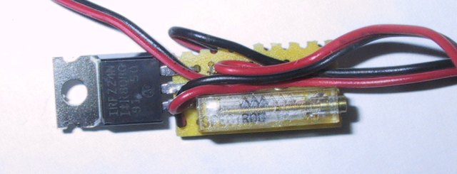
The MOSFET can be just about any N-channel Power MOSFET, as long as it can handle the 12 V voltage and the amperes the fan requires. Even the cheapest Power MOSFETs in the $1 area can usally handle over 50 V and over 10 amperes, so they will be by far sufficient for this circuit. We used an IRFZ24N MOSFET. If you're in the US, you can use an IFR510 Power MOSFET. The pinout of Power MOSFETs is standardized, as you can see on the image. It is very unlikely that the MOSFET you buy has a different pinout, unless you get a really exotic one.
The spindle trimming potentiometer should be a 10K type. If you cannot get a 10 K unit, 20 K or 25 K will also do. However, this pot is rather large and bulky, a spindle trimming potentiometer is really the more elegant (and also cheaper) solution. Finally, for the NTC thermistor, get the cheapest 10K NTC you can get. It doesn't matter if it has a high tolerance. You can also use the flat thermistors for CPU monitoring that ship with some motherboards.

Apart from the electronic parts, you should also get:
- Heat-contractable tubing
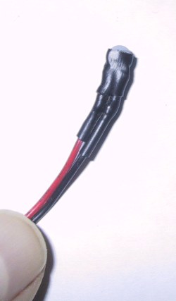
Since the unit is so small, you don't need to put it in a special case. However, it is absolutely required that the entire unit is insulated. Otherwise, it might cause a short circuit when touching your case (see warning below). The easiest and cheapest solution is to simply put all the circuitry in a (large enough) heat-contractable tube. If you have trouble getting heat-contractable tubings that are large enough, you can also wrap up the circuit with good old electrical tape. Also, the NTC's contacts must be insulated (see photo). For this, you need smaller heat-contractable tubing. Since this tubing also provides som thermal insulation, the wisest thing to do is to apply it in a way that the head of the NTC sticks out, but the contacts are insulated - see photo.
- A little PCB
Since we're dealing only with three components, it's not strictly necessary to put them on a PCB. However, it is more elegant to use a PCB, and it makes things easier.
- Possibly a heatsink for the MOSFET
Under normal conditions, it is not necessary to put a heatsink on the MOSFET. However, if you'd like to use the temperature control for an unusually high load (more than three fans, or fans with particularly high power usage), then you should add a little heatsink to the MOSFET. Again, the heatsink must be insulated. Depending on where you buy the parts, the total price of all parts of the temperature control will be between $3 and $6. Feel free to use the Heatsink Guide Discussion Board for help, suggestions, tips for places to buy, and "coshopping".
Assembling it
I won't be bothering you with complicated electronic symbols - instead, I've drawn all the components the way they really look, to make it as easy as possible for you. This way, you can build the circuit without any knowledge about electronics - as long as you know how to use a soldering iron. Note that the NTC is shown larger than it is in real life.
When it's done in an elegant way, the entire circuit can be as small as you can see on these photos:
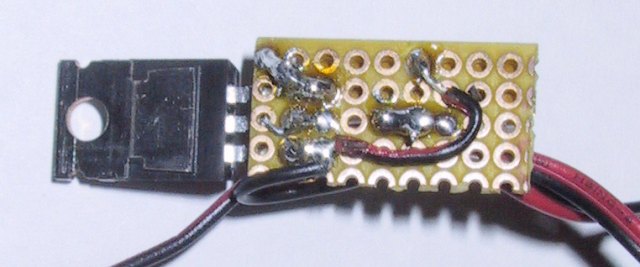
However, if you're not very experienced with soldering, I'd recommend to build the thing on a larger PCB. Before you start testing your device, read the following warning:
WARNING! Whenever you're building an electric or electronic device, good insulation is very important for security. This temperature control isn't an exception. All parts of the temperature control, including the sensor and the MOSFET transistor (even it's metal backplate!) carry a voltage of up to 12 V. Therefore, it is absolutely required that the circuit is properly insulated (e.g. using heat-contractable tubing or electrical tape). If the unit is not properly insulated, a short circuit will occur if the circuit or the sensor touches the case or (even worse) the motherboard.
Fan RPM monitoring will NOT work with this temperature control. Don't try to connect the rpm signal wire to your motherboard. It will not work and might damage your motherboard. Building a temperature control that works with rpm monitoring would require the usage of a P-Channel MOSFET (and a different circuitry), which are not as widely available as N-Channel Power MOSFETs.
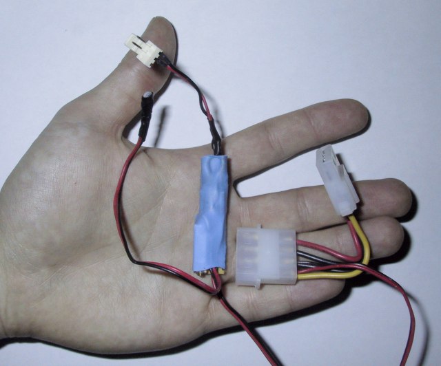
Here's the finished unit with proper insulation. The potentiometer's screw sticks out on the lower end.
Setting up the temperature control
Before you start using the temperature control, the temperature at which the CPU (or case, etc...) should be kept must be set. This is done by adjusting the spindle trimming potentiometer. A good strategy to do this is: Start with a cool CPU (or case). Turn potentiometer until the fan doesn't spin at all. Then, watch the temperature rise. As soon as the temperature gets close to the maximum it should reach, adjust the potentiometer so that the fan just starts to spin.
Exact adjustment is crucial if you'd like your temperature control to work the way it should. Do invest enough time adjusting it precisely. If the adjustment is not good, the computer will either overheat, or the fans will spin almost at top speed all the time, making the control useless.
You might notice that when turning your computer on, the controlled fans will not spin at all. After a while, as the system gets hotter, they will start to spin; and often they will spin a little faster at first, but then fall back to slower speed after a while. This is normal; the reason is that fans need a higher voltage to start spinning than to keep spinning.
If you change the fan connected to the temperature control, or if you add another fan, the temperature must be readjusted.
Legal stuff
If you build this temperature control, you do it at your OWN RISK. The instructions presented here come with NO WARRANTY, neither expressed nor implied.