Sundaresan Sundararaj
Electronic Design
This idea describes a white-LED (WLED) driver circuit controlled by a simple ambient light sensor (ALS). A typical application would be a brightness control for cell-phone backlighting. On a very sunny day, the brightness will increase to improve the overall visibility.
The circuit uses the IA2505 four-channel WLED (Fig. 1). Each LED can be driven up to 20 mA, with the drive current determined by the current sourced through the resistor (RSET) pin. RSET is a constant voltage source set at 1.2 V.
 |
||
| Figure 1. | An ambient light sensor based on a pseudo logarithmic amplifier is a simple way to control the driver current for a white-LED array. |
|
A resistor between the RSET pin and GND would set a fixed current equally distributed through the four WLEDs irrespective of the ambient light conditions. However, because ambient light isn’t constant in the real world, replacing the RSET with the ALS gives you automatic brightness control.
The ALS, which is basically a pseudo logarithmic amplifier, employs an operational amplifier (IC2) and a signal diode (D3). A log amplifier is employed because of the large dynamic range of photo current.
The circuit is designed for 1 μA to 1 mA (60 dB) of photo current. The photodiode, an infrared PIN photodiode, operates in reverse-bias mode as shown in Figure 1. All ambient light sources (fluorescent or incandescent bulbs and sunlight) contain a significant amount of infrared light. Ideally, a photodiode sensitive to visible light would be the best option.
|
||||||||
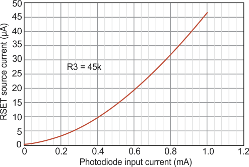
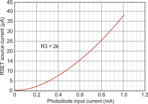
| Figure 2. | These graphs show how the RSET source current varies with changes in the photodiode (D2) input current for R3 = 45 kΩ (a) and R3 = 2 kΩ (b). |
|||||||
The bias pot (R3) varies the sensitivity of the ALS depending on the ambient light available and respective photo-current range. For maximum brightness (80 mA total), RSET should source 66 μA through the transistor (T1). The RSET source current is mirrored with a gain of 1200 internally by the IA2505 to drive the four LEDs.
Figure 2 shows the transfer function between the photo current and RSET source current for an expected photo current range (R3 = 45 kΩ and R3 = 2 kΩ).

