Marc Ysebaert
EDN
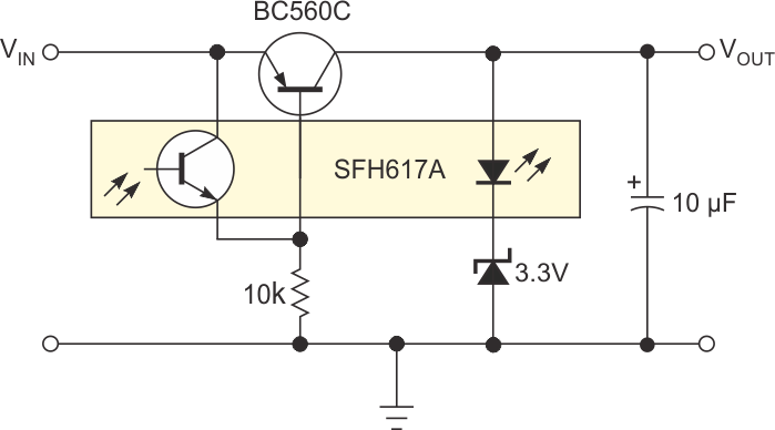
Although a monolithic low-dropout regulator has superior dynamic characteristics, the discrete regulator in this Design Idea is so simple that you can adapt it to many purposes. Using a common transistor, it has a dropout voltage of 0.1 V. This dropout voltage can be even less if you use a FET. In the circuit in Figure 1, the optocoupler’s LED determines the approximately 1 V output voltage, which the circuit adds to the voltage of the zener diode. A low-current zener diode gives the best results because regulation occurs at less than 1 mA, depending on the current gain of the transistor. To regulate the voltage of one battery cell, you can omit the zener diode to a given output voltage of approximately 1 V. You can also replace the zener diode with a potentiometer to obtain a variable output voltage. Another alternative is to use a combination of one or more LEDs or regular or Schottky diodes to obtain a fixed output voltage. You can insert a low-current LED as part of the voltage-reference branch to give an indication of the proper operation of the regulator.
 |
||
| Figure 1. | This simple low-dropout circuit is ideal for higher voltages that a zener diode sets. |
|
The circuit in Figure 1 consumes approximately 1 mA and starts to limit the current at currents higher than approximately 50 mA. With a lower value for the resistor, the LED glows brighter, the output voltage is slightly higher, and the current consumption and the current limit are proportionally higher. You can replace the transistor and the optocoupler with almost any other type, but a high current gain and transfer ratio are preferable. When you use a high-voltage transistor, the input voltage can be much higher than is possible with common monolithic regulators. You can use a Darlington transistor for higher currents if your design can tolerate a dropout voltage of 0.7 V. An output capacitor with a value of approximately 10 to 47 μF is necessary to avoid oscillation. Higher values are necessary for higher output currents. The circuit requires no input capacitor.
 |
||
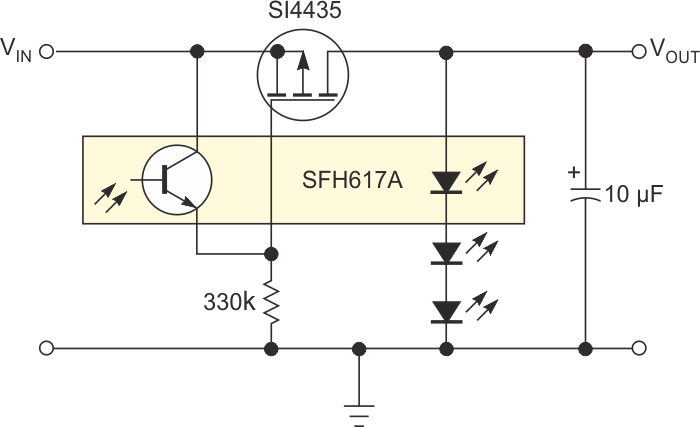
| Figure 2. | Using LEDs or diodes makes the circuit suited for lower regulation voltages. |
|
The circuit in Figure 2 replaces the transistor with a P-channel FET and uses a 330-kΩ resistor. In this configuration, the circuit consumes about 50 μA and should suit many battery-powered devices. There is no inherent current limiting. You can reduce R1 to 10 kΩ or lower to have a faster response to load change and to obtain a visual indication with the LEDs.