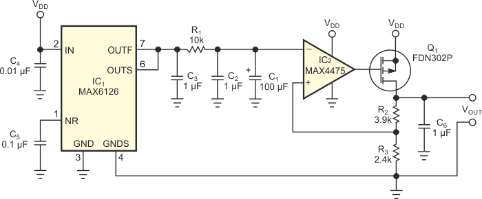
Many low-dropout-voltage regulators see service in electronic systems, but relatively few are designed for low-noise operation. (For example, Maxim's MAX8887 achieves a noise voltage of approximately 42 µV rms.) However, certain applications, such as ultra-low-noise instrumentation oscillators, demand even lower levels of power-supply noise. To reach this level, the circuit in Figure 1 combines low-noise components and extra filtering to achieve an output noise floor of only 6 nV/√Hz.
 |
|
| Figure 1. | This low-dropout-voltage regulator features a noise floor of only 6 nV/√Hz, making it an ideal power source for low-noise oscillators. |
Voltage reference IC1, a Maxim MAX6126, features low output noise. Lowpass filter R1-C1 further reduces this noise by attenuating noise frequencies above IC1’s 0.16-Hz cutoff frequency. The filtered reference voltage drives the inverting terminal of error amplifier IC2, a Maxim MAX4475, which regulates the output voltage by means of Q1, a P-channel power FET source follower. Feedback resistors R2 and R3 determine the output voltage as follows:
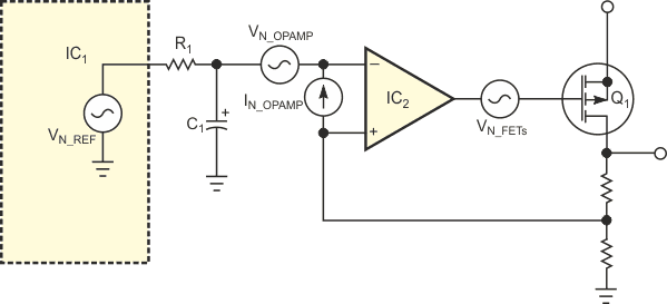
The simplified noise-analysis diagram illustrates the components' noise contributions (Figure 2). Lowpass filter R1-C1 attenuates high-frequency noise on the voltage reference's output. The op amp's noise current, 0.5 fA/√Hz, is negligible with respect to its voltage noise, 4.5 nV/√Hz. The reference-noise source adds to the op-amp voltage noise because they effectively connect in series. The MOSFET's noise contribution appears at Q1’s input.
 |
|
| Figure 2. | This simplified version of Figure 1 highlights noise sources for analysis. |
The noise at IC2’s inverting terminal equals the noise at its noninverting terminal:
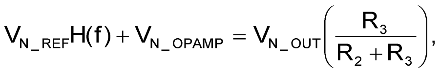
and
where
VN_OUT represents the low-dropout circuit's output noise,
VN_REF represents the reference noise,
VN_OPAMP represents the op amp's input-referred noise,
H(f) represents the R1-C1 lowpass filter's transfer function.
If a noise frequency of interest falls well below the filter's cutoff frequency, the reference noise is negligible, and the low-dropout circuit's output noise comprises only the op amp's noise multiplied by the closed-loop gain. The feedback loop suppresses VN_FET, the MOSFET's noise contribution, which therefore can't contribute to the output noise. For frequencies within the loop's bandwidth, the low-dropout circuit also rejects ripple and noise voltages that the power supply introduces.
 |
|
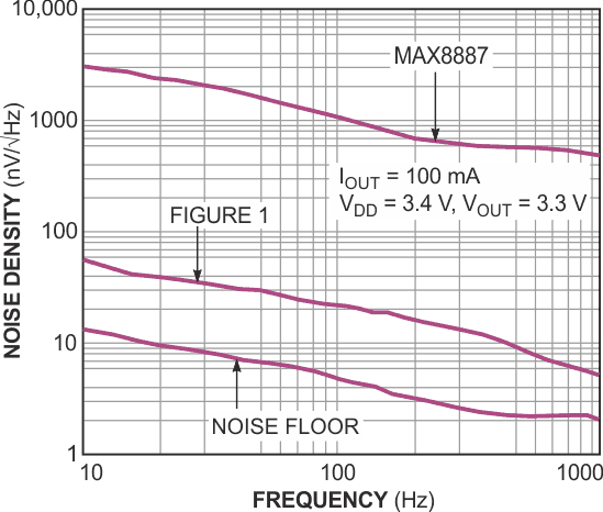
| Figure 3. | A noise-density-versus-frequency plot for the lowdropout circuit in Figure 1 is 38 dB lower than that of a conventional low-noise, low-dropout-voltage regulator – in this case, a Maxim MAX8887. |
Figure 3 shows a plot of noise density versus frequency for the circuit of Figure 1, which exhibits a noise floor of about 6 nV/√Hz at 1 kHz. For comparison, the plot shows the noise-measurement instrument's noise floor and a typical low-dropout circuit's much higher noise density – for example, 500 nV/√Hz at 1 kHz for the MAX8887 low-noise, low-dropout circuit.