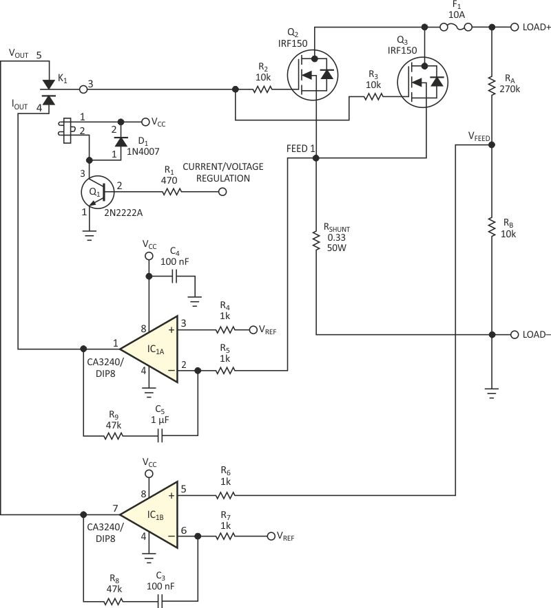
Designers use electronic dc loads for testing power supplies and sources, such as solar arrays or batteries, but commercial ones are often expensive. By using a power MOSFET in its linear region, you can build your own (Figure 1). It uses two simple feedback loops to allow the transistors to work as a current drain in current-regulation mode or as a voltage source in voltage-regulation mode. Designers use current-regulation mode when they are characterizing voltage sources, in which the power source must deliver current value that is set in the electronic load. They use voltage-regulation mode with current sources because it forces the sources to operate at a voltage that the load sets.
 |
||
| Figure 1. | Using MOSFETs and a relay, this electronic load can operate in both current- and voltage-regulation modes. |
|
In current mode, RSHUNT senses ILOAD, and the resultant voltage feeds back to the inverting input of op amp IC1A. Because the dc gain of this amplifier is high in the linear-feedback operating range, the inverting input stays equal to the noninverting input, which corresponds to VREF. The amplifier establishes its output value to operate MOSFETs Q2 and Q3 in a linear region and, therefore, dissipate the power from the source. The value of the source current is proportional to the current-loop reference, VREF, and is
Set VREF using a resistive voltage divider connected to a stable reference, or use the output of a D/A converter from a PC-based I/O card for flexible configuration.
Voltage-operating mode is similar, but now the sensed variable is the output voltage, which voltage divider RA/RB attenuates, so that the electronic load can operate at higher voltages than the op-amp supply voltage. The sensed voltage feeds back to the noninverting input of IC1B, and the MOSFETs again operate in the linear region.
Load voltage
The dual-op-amp CA3240, IC1, can operate with an input voltage below its negative supply rail, which is useful for single-supply operation, but you can use any op amp if you have a symmetrical supply. Relay K1 switches operating mode through a digital control line driving Q1. The MOSFET is critical; you can add the IRF150 devices this design uses in parallel to increase the current-handing capabilities due to their positive-temperature coefficient, which equalizes the current flowing in the parallel MOSFETs. With the two MOSFETs in the circuit, the load handles 10 A, and power consumption is greater than 100 W, so using a heat sink and small fan is a good idea.
 |
||
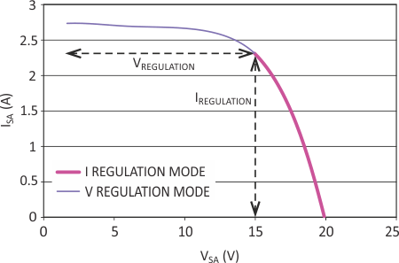
| Figure 2. | The I-V characteristics of a photovoltaic module, using the electronic load, show the special attributes of these power sources. |
|
This circuit is useful for characterizing photovoltaic modules, which have two source modes. With this circuit and a PC-based setup, the I-V characteristic of a photovoltaic module from Helios Technology shows a region above VMPP (voltage in the maximum point), at which a sharp transition corresponds to a voltage source (Figure 2). At voltages below VMPP, the photovoltaic modules look like a current source. It is normally difficult to characterize this flat region of the curve with a simple current-mode electronic load, because the voltage output is sensitive to small variations in current, and thus a constant-voltage mode load is a better choice.