In this post I will try to show, why it's a good idea to use a current limiting resistor for an LED. And when it's save to drive the LED without any resistor. If you read about LEDs, you will notice that everyone tells you, that you need a current limiting resistor. But mostly they do not tell you why. LED with current limiting resistor If you look at a datasheet of an LED, you will notice that graphs shown are not linear. An LED is a diode, a semiconductor and behaves differently compared to a resistor.
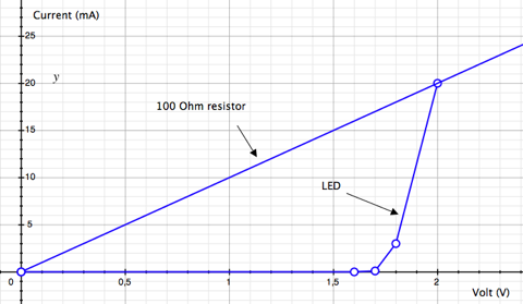
If you apply a specific voltage to a resistor, you can compute the resulting current with: I = R/V Example: I = 100 Ohm / 5 Volt = 20 mA Obviously that does not work with LEDs because they don't behave like a linear resistor. If you look at the graph above, you can rise the voltage from 0 Volt to 1.6 Volt without resulting in noticeable current. Apply a bit more voltage and there is current and the LED lights up. We have reached the Forward Voltage which is needed to open the pn-gate. Forward Voltage (VF) for a typical red LED is 1.7 to 2.2 Volt. Now small changes in the voltage produce large effects on the resulting forward current (IF). Datasheets normally state at least the absolute maximum ratings for IF, eg. 25 mA. If you apply a voltage that results in a larger current, the LED may be destroyed. So it's vital to stay within the limits of the LED. If you would attach an LED to a 5 Volt power supply directly, you would burn it instantly. The high current would destroy the pn-gate. That's the point where the current limiting resistor comes in.
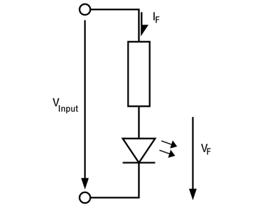
Assuming, we have a red LED with maximum rating of IF: 25 mA at VF: 2.1 Volt. If we want to use it at 5 Volt, we have to use a resistor to dissipate the remaining 2.9 Volt. To compute the resitor, we use: R = V / I = (5 Volt - 2.1 Volt) / 25 mA = 116 Ohm. To be safe we use a 120, or better, 150 Ohm resistor. That way we don't drive the LED near it's maximum rating. R = V / I = (5 Volt - 2 Volt) / 20 mA = 150 Ohm. To be safe with the resistor, we have to take a look at the power dissipation. It calculates as: P = V * I = 3 Volt * 20 mA = 60 mW So it's safe to choose a 150 Ohm resistor with 1/4 Watt rating. Ok, so far the typical use of an LED with an current limitting resistor. LED without current limitting resistor First of all, why would you want to get rid of the resistor? There are two reasons. First is, it wastes energy. It converts electrical energy into heat. But we want to light up an LED. Not good. Second is, you can reduce the number of components.
The circuit gets cheaper, because we saved a resistor and maybe space on a PCB. There are two ways to bypass the resistor. One way is to lower the input voltage. If you are able to run your complete circuit with the same voltage as forward voltage of the LED, perfect. No resistor needed. Another method is to use pulse width modulation (PWM). That means we are switching the LED on and off. If we are switching fast enough, the human eye can not tell the difference. It integrates the brightness over time, so to speak. Often there is a Peak Forward Current (IF(peak)) rating in the datasheet. As an example: IF(peak) = 160 mA Condition: Pulse Width <= 1 msec and Duty <= 1/10 Which means, it is safe to switch the LED with 1 kHz, where the LED is on for 1 msec and off for 9 msecs. Most of the times there is no voltage given for IF(peak), so we can not be sure at what voltage we will reach the 160 mA in the example. Looking at the graph, I would assume that you could go up to 3 V, maybe 3.2 V, but I haven't tested it out. I used both methods for my 64pixels, where I attached an LED matrix directly to a microcontroller without any current limitting resistors.
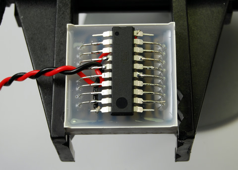
The input voltage is 3 Volts, if used with 2 AA batteries or about 2.4 Volts with 2 AA rechargeables. That helps to get closer to VF of the LEDs. The matrix lets you address only one row at a time. So you set all column bits for row one and enable row one. Then you disable row one, set all bits for row two and enable row two, and so on. So you are cycling through all rows. This is done so fast, that you wont see any flickering. Every row is updated with nearly 2 kHz and with a duty cycle of 1/8 (because of the 8 rows).
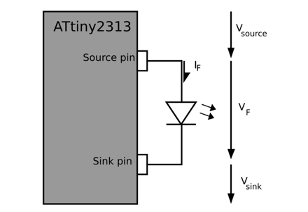
If you are using a microcontroller for driving an LED or LED matrix, you have to take care of the current ratings of the microcontroller as well. Every I/O pin can only deliver (source) or receive (sink) a specific amount of current. I used an ATtiny2313 and from the datasheet on page 181, I read Absolute Maximum Ratings: * DC Current per I/O pin: 40.0 mA And on page 182 as a note: 4. Although each I/O port can sink more than the test conditions (10 mA at VCC = 5V, 5 mA at VCC = 3V) under steady state conditions (non-transient), the following must be observed: 1] The sum of all IOL, for all ports, should not exceed 60 mA. If IOL exceeds the test condition, VOL may exceed the related specification. Pins are not guaranteed to sink current greater than the listed test condition. As I understand that, if you are trying to source or sink more than 10 mA, the voltage VOL (Output Low Voltage) or VOH (Output High-voltage) may drop or rise and exeed the specified values. Looking at two graphs from the datasheet may help to clear things up.
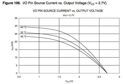
This figure shows how the output voltage of a source pin is related to the current that it sources at 2.7 V input voltage. 2.7 is not 3 Volts as 2 AA cells can deliver, but close enough for now. What we see, is that the output voltage drops, if we demand more and more current. At 5 mA we have a voltage of 2.5 Volts, but at 15 mA the voltage drops to 2.1 Volts.
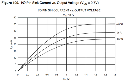
This figure shows how the output voltage of a sink pin is related to the current that it sinks. This time the ouput voltage rises, if we demand the pin to sink more current. At 5 mA the voltage is 0.15 Volts but rises to 0.5 Volts at 15 mA. To check if we are using the ATtiny2313 and the matrix within their specifications, we have to do some math. For the matrix, there is no datasheet with nice graphs but some numbers. Forward Voltage: 1.80 - 2.20 V Maximum Rating: Forward Current: 25 mA We assume the LED runs at 1.8 Volts with 5 mA. That looks reasonable when you take a look at other datasheets. Now, if we insert the 5 mA into the two figures above, we get: 2.5 Volt for the source pin and 0.15 V for the sink pin. 2.5 V - 0.15 V = 2.35 V So we get that 2.35 V is left for the LED.
That is more than we have assumed (1.8 V). Higher voltage for the LED means more current. So this time we will compute with 10 mA. Inserting that again, we get 2.3 V for the source pin and 0.3 V for the sink pin. 2.3 V - 0.3 V = 2.0 V As you see, if the voltage over the LED rises, the current through it raises as well. But the rising current results in lower/higher output voltage from the source/sink pin. And that means lower current. It is, as if they are fighting each other. 2.0 V at 10 mA looks ok for the LED and the microcontroller. That was one LED on two I/O pins. What, if we want to control a complete row of eight LEDs? This time eight source pins, eight LEDs and one sink pin. From the example above, 10 mA per LED sums up to 80 mA (!). That's a lot. Looking it up on the figure is not even possible. Lets assume, it all sums up to only 25 mA, that would be 3.125 mA per LED. That gives us 2.6 V at every source pin and 1.0 V for the single sink pin. 2.6 V - 1.0 V = 1.6 V That means, 1.6 V is left for every LED, we are a bit beneath the forward voltage of the LED.
So the LED may be a bit dimmer. Again, if the LEDs would suck more current, the microcontroller would deliver less output voltage for the LEDs. If you look thoroughly at the 64 pixels display, you may notice, that the rows with few pixels lit are a bit brighter than the others. After all this computing and datasheet staring I think it is safe to let out the current limiting resistor in some cases. You have to take a closer look at specs to get an idea on how it will work out. If I get something wrong or mixed things up, please feel free to comment on this.