Alan Ball, ON Semiconductor
PowerPulse
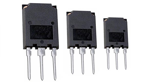
As the demand for high power electronic equipment grows, it becomes necessary to drive high-voltage, high-current loads. Achieving high levels of both voltage and current in a switching power converter often requires paralleled switching devices, such as IGBTs which are well suited for this type of application.
There are a number of issues to be considered when connecting two or more IGBTs in parallel. One of those issues is the interconnection of the gates. Paralleled IGBTs can use a common gate resistor, separate ones or a combination of those two scenarios. Most discussions on this topic offer the opinion that separate gate resistors are a must. However, there is a strong case for a common gate resistor.
 |
|
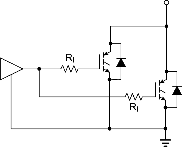
| Individual Gate Resistors | |
 |
|
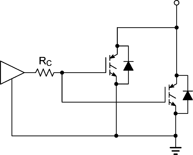
| Common Gate Resistors | |
 |
|
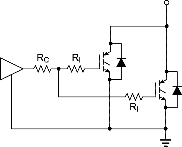
| Combination Gate Resistors | |
| Different configurations of IGBT gate resistors |
When determining the drive scheme for paralleled IGBTs one of the first things to consider is the total amount of drive current required. If a suitable driver is not available to drive the total base current of the IGBTs that are connected in parallel, the IGBTs will have to be driven by individual drivers. In this case each IGBT will have to have its own gate resistor. Most drivers are sufficiently fast to apply the turn on and turn off pulses within 10 s of nanoseconds of each other. This is quite adequate for IGBT timing as they typically switches in a few hundred nanoseconds.
If a single driver is used then the discussion can focus on the configuration of the gate resistors. The downside to individual gate resistors is that mismatches in the timing can be increased since the drive voltage on the gates will not track at turn on and turn off. Even though the gate pulses at the driver end of the resistors will be exactly the same, the variance in gate charge of the IGBTs combined with the gate resistance and circuit board impedances will create varying rise, fall and delay times at the gates of the IGBTs. Still, many sources advocate the use of individual gate resistors as they will minimize the possibility of oscillations between IGBTs.
Oscillations can occur due to the stray inductance (mainly in the emitter circuit) of the layout, combined with the gate capacitance and gain of the IGBTs. Minimizing the inductance in the emitter circuit, will go a long way toward eliminating parasitic oscillations.
A common gate resistor assures that both gates are at the same potential at any given time, with only a very small difference due to parasitic variations in the impedance path. This can reduce differences in losses and help IGBTs to share current more equally during the switching transitions. Common or individual gate resistors have no effect on the DC current levels as all of the IGBT gates will eventually charge up to the gate bias voltage. The use of a common gate resistor has been suggested by other sources also, but is not as common of a guideline as individual gate resistors.
To test the gate resistor configuration options, two IGBTs were chosen from a group of 22 parts. The two chosen devices were selected for their mismatch. The devices tested were NGTB40N60IHL IGBTs manufactured by ON Semiconductor. These are 600 volt, 40 amp devices. Units 1 and 26 were selected for their differences in both parameters. Their turn-on losses were 1.65 mJ and 1.85 mJ respectively and their turn off losses were 0.366 mJ and 0.390 mJ respectively.
Using a single driver and separate 22 Ω gate resistors, the imbalance in the current waveforms at turn off was quite noticeable and was due to the mismatch in switching speeds along with differences in the threshold, transconductance and gate charge characteristics for the two devices. Substituting a common 11 Ω gate resistor forces both gates to be at the same potential at any given time. The imbalance at turn off is greatly reduced with this configuration, and the DC imbalance is not affected by the configuration of gate resistors.
Since the possibility of oscillations between devices can not be determined until the system is designed and a prototype built, it is recommended that a gate circuit be used that can accommodate individual, common and a combination of gate resistors.
The combinational schematic offers the flexibility of adjusting the values of the gate resistors based on the parasitic impedances of the actual circuit. If some oscillation is observed with a common resistor, the resistive gate impedance can be divided into a common and an individual component. For optimum performance, the individual resistors should account for as much of the gate resistance as possible without the risk of oscillations. This circuit can easily be tuned in a functional unit under a range of operating and environmental conditions. In this manner, the gate voltages can be held as close as possible to the same potentials during turn on and turn off, but some individual resistance can be added when necessary to assure that the devices do not oscillate with each other.
Achieving optimal performance in a high-power, parallel application allows for maximum system reliability and maximum performance. The gate drive considerations discussed herein, are one of the factors that will optimize a high-power switching system.