Digital potentiometers (dpots) are ubiquitous components available in a variety of packages, resistances, and resolutions. However, few implement anything but the usual linear function of resistance vs. setting. This fact makes trouble for applications that need a wide (i.e., multiple decades) dynamic range of gain adjustment.
Imagine, for example, an amplifier with gain that you set over a range of 0 to 10,000 (80 dB) using an 8-bit (1 in 256) resolution pot. With a linear relationship between potentiometer setting and resistance (linear taper) there will be a linear relationship between dpot setting and gain. One step in each of the 256 pot settings represents a gain change increment of roughly 40 (i.e., gain steps will be 0, 40, 80, 120, 160, etc.).
For dpot settings of 8 or above (gain >300) this provides reasonably good resolution in gain settings, allowing gain control of 1 dB or less per step. Below a setting of 8, however, gain resolution deteriorates badly. If you need to set gain to 100 or less, for example, you can forget about hitting the necessary value with any meaningful accuracy. Your only choices would be around 80 or around 120.
If an accurate, stable, high resolution digital pot with a logarithmic taper (log of resistance proportional to setting) were available, it would be easy to arrange a gain-control circuit that provided a constant resolution in dB/increment over the full adjustment range. Unfortunately, logarithmic digital pots (log dpots) with good resolution (e.g., < 6 dB per step) don’t exist.
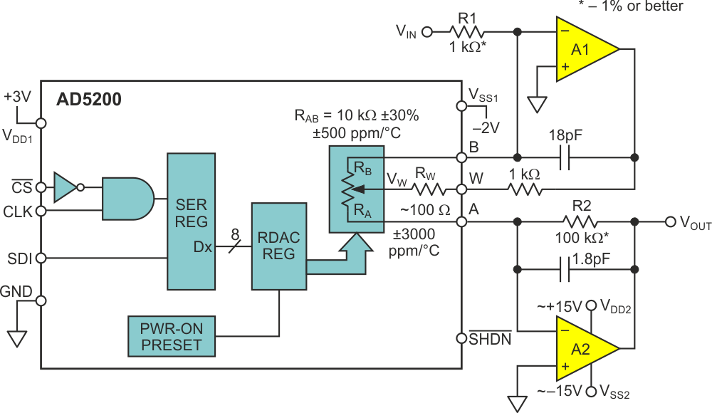
But all is not lost. The Design Idea presented in Figure 1 implements an approximate logarithmic gain control with an ordinary linear-taper pot (e.g., ADI’s inexpensive bipolar AD5200).
 |
||
| Figure 1. | Linear digital pot simulates log taper. | |
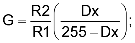
If Dx (above) represents the wiper setting (0 – 255), solving the design equation for amplifier gain VOUT/VIN vs. Dx is easy if we do it piecemeal. First, solving for wiper voltage (VW) as a function of VIN:
 |
(1) |
Next, solving for VOUT as a function of VW:
 |
(2) |
Then combining equations 1 and 2:
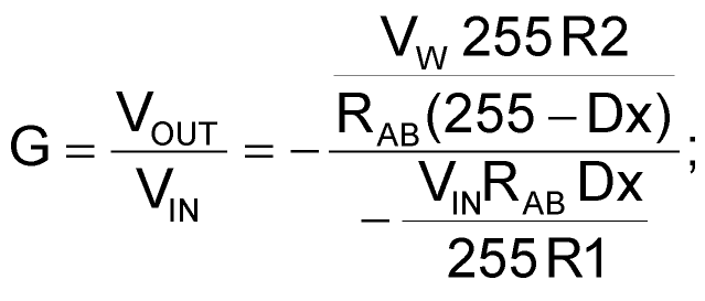 |
(3) |
where G is the gain.
 |
(4) |
 |
(5) |
And, of course:
 |
(6) |
 |
(7) |
We get:
 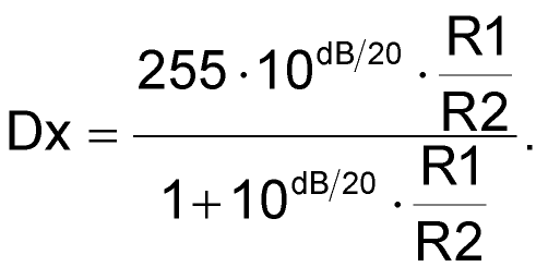 |
(8) |
Interesting features of the resulting gain equations include:
 |
||
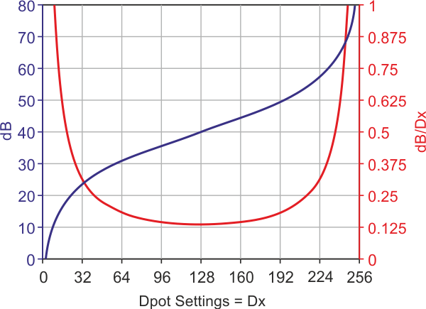
| Figure 2. | dB gain (y-axis at left) and gain set resolution (y-axis at right) vs. Dx (x-axis). | |
- The promised (approximate) logarithmic behavior of Dx/(255 – Dx). As shown in Figure 2, with R2/R1=100, Dx = 8 gives gain »10 dB; Dx = 23 yields 20 dB; 128 gives 40 dB; 232 gives 60 dB; and 247 gives 70 dB. That gain-setting resolution remains no worse than 1 dB over the entire 60 dB =1,000-to-1 range is especially significant. Additionally, Dx = 0 sets a gain of zero while Dx = 255 selects open-loop.
- The gambit of using the potentiometer wiper as an input terminal effectively moves the wiper contact inside the feedback loop of amplifier A1 (Figure 1), thus removing it as an error term and improving the time and temperature stability of the gain setting.
- Meanwhile, using the RAB resistance element for both A1 feedback and A2 input (Figure 1) ratios out sensitivity to both RAB tolerance and temperature coefficient (tempco) (±30% and 500 ppm/°C in the AD5200), leaving R1 and R2 as the sole dominant factors in gainset accuracy.
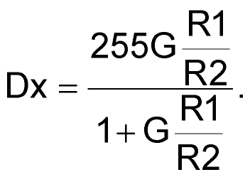
- If better than 8-bit (1/256) resolution is desired, parts like the 10-bit AD5292 can be dropped into the topology for 4× higher gain setting precision. Just remember to substitute 1023 wherever 255 appears in the gain equations! Or, more generally, if N = number of bits:
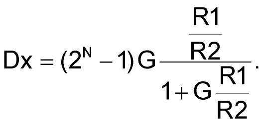 |
(9) |