Derek Bowers
Electronic Design
Early radio receivers and record players nearly always had a knob marked “tone,” which was usually a crude low-pass filter with some form of severity adjustment. At best, these controls could partially compensate for bass loss caused by poor speaker baffling. More sophisticated controls were developed for more modern equipment, including the bass/treble (Baxandall) controls, parametric equalizers, and graphic equalizers.
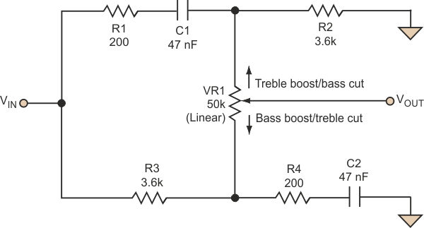
Nevertheless, a single-adjustment tone control often can be useful for fine balance adjustment or where multiple controls are impractical or unnecessary. A simple version of such a control provides a symmetric response that is flat at the center of the adjustment range (Fig. 1).
 |
||
| Figure 1. | This simple circuit allows single-adjustment tone control for fine balance adjustment or applications where multiple controls are impractical. |
|
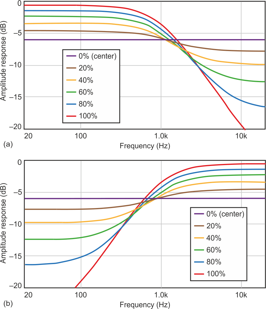
Moving the control in one direction simultaneously boosts the treble and cuts the bass until about 5.5 dB of boost and 23 dB of cut are obtained. Moving the control in the other direction boosts the bass and cuts the treble in an identical fashion. Figure 2 shows the typical curves obtained from 20 Hz to 20 kHz with a 1-kHz center frequency, for the lower half and upper half of the control range, respectively.
 |
||
| Figure 2. | The tone-control circuit delivers good response characteristics in both the lower half (a) and upper half (b) of the control range. |
|
Naturally, for stereo, the circuit would be duplicated and VR1 substituted with a dual, ganged component. Since the circuit is purely passive, it is easy to insert in the signal chain. However, it must be preceded by a low impedance (below 100 Ω) and followed by a high impedance (more than 250 kΩ) for best results. Under these circumstances, insertion loss (at center) approaches 6 dB.
Since this is a purely passive circuit, all component values may be scaled without affecting the ac transfer function. With lower resistor values (and higher capacitor values), the signal-to-noise ratio improves, but the circuit requires a lower impedance to drive it. The values shown represent a good compromise. Overall signal-to-noise ratio in a 20-kHz bandwidth is about –113 dB referenced to 1 V rms with the control in the center position.