Chris Glaser, Texas Instruments
Electronic Design
The thermoelectric cooler that stabilizes the temperature of a laser diode needs a special power-supply configuration, which is provided by this simple circuit.
A most critical device in an optical networking system is the laser diode, since it’s responsible for converting the electronic data to light pulses. This diode must be carefully controlled to stabilize the light output, and temperature is a key variable to determine the light’s wavelength. Thermoelectric coolers (TECs) are commonly used as part of this stabilization process. Since TECs come in many different power levels and have unique power requirements, a specific type of power supply is required to drive them properly.
A TEC transfers heat energy from one plate to another to make the first plate cooler or warmer. A TEC doesn’t consume energy itself; in other words, no energy is lost, but energy is required to operate the TEC. A TEC is modeled as a simple resistor that can withstand a certain voltage across it and current through it. This power corresponds to a maximum temperature difference between the two plates for a given TEC. The higher the power applied, the higher the temperature difference between the plates.
An important aspect of TECs is their ability to both heat and cool. Since a TEC is permanently mounted or attached to the laser or other device needing temperature regulation, only one plate controls the laser’s temperature. The other plate must be mounted to a heat sink to release the energy moved from the first plate. Both plates require very good thermal connections for best system performance.
Once installed in a system, the plates cannot be reversed. The TEC must support cooling and heating from a given orientation. TECs support this complementary function by controlling the direction of current flow. Current flowing in one direction cools one plate and heats the other, while current flowing in the reverse direction reverses this action, heating the first plate and cooling the second one. The result is a wider range of temperature control compared to current flowing in one direction only.
Since TECs require bidirectional current flow to achieve the desired performance, their power supply must support this dual mode as well. However, many power supplies can only source current. Therefore, a special circuit needs to be designed to swap the connections from the power supply to the TEC when cooling is needed versus heating, which complicates implementation of the supply.
An alternative approach is to design a power supply that can both source and sink current with unchanged connections to the TEC, thus meeting the current-flow requirements. However, only some power-supply designs support both sourcing and sinking current. In addition, the supply must support operation near a zero-current value, which is a common operating point.
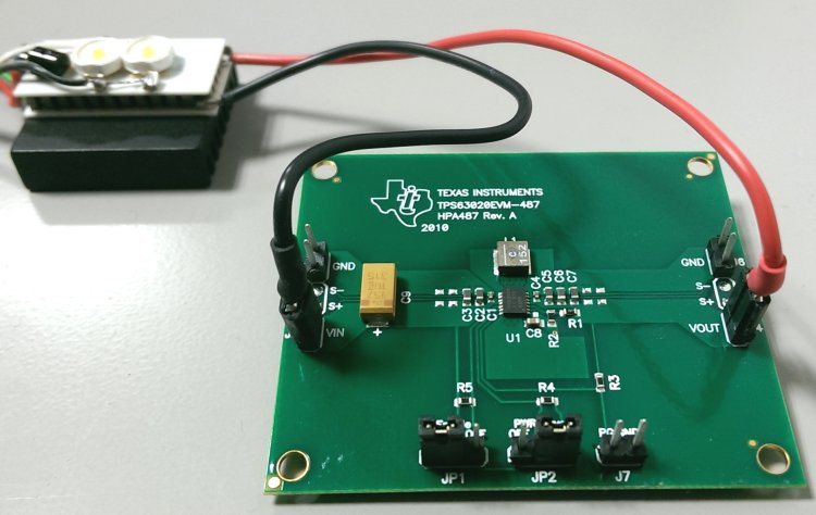
The power-supply in Figure 1 is a circuit that can source and sink current for a low-power TEC. For example, a buck-boost converter such as the TPS63020 is used to either buck or boost the supplied input voltage in order to generate the desired current-flow direction. The topology of a buck-boost converter supports a wide output-voltage range, in this case from 1.2 to 5.5 V.
 |
|
| Figure 1. | Shown is an example of a simple circuit (TI reference design PMP9759) that bidirectionally drives current through a TEC; the single-chip buck-boost converter requires a minimum number of components. |
By integrating all power MOSFETs and requiring a minimum of external components, this circuit is a more preferred approach for low-power TECs where size is critical, such as in the smallest optical-networking modules. The buck-boost converter is powered from the common 3.3-V rail found in optical networking modules. The TEC’s connections to the power supply (Figure 2) allow a +2.1- to –2.2-V voltage difference across the TEC. Furthermore, the commonplace operating point near zero-current is easily supported in this configuration.
 |
|
| Figure 2. | This circuit generates a bidirectional current flow through a TEC with just one converter and a few passive components. |
TEC orientation is critical to its heating or cooling. Modern electronics often appear to be somewhat warm and easy to further heat up. However, it’s usually more difficult to cool a TEC enough to achieve the desired laser wavelength. Therefore, it's better to wire the TEC so that it’s cooling when the buck-boost converter is sourcing current. The TPS63020, like many converters that both source and sink, can source more current than it can sink. Therefore, it can deliver a smaller amount of power when sinking, so sinking current should be used to heat the TEC.
 |
|
| Figure 3. | In a complete closed-loop TEC temperature-regulation circuit, the MCU reads the temperature sensor and generates an output control signal to the buck-boost converter to adjust the TEC’s temperature appropriately. |
In the complete system (Figure 3), a microcontroller (MCU) monitors a temperature sensor on the TEC. Based on the TEC’s actual-versus-desired temperature (the setpoint), the MCU adjusts the control signal (VCTRL) to move the buck-boost converter to a new operating point, sourcing or sinking more or less current to adjust the temperature.