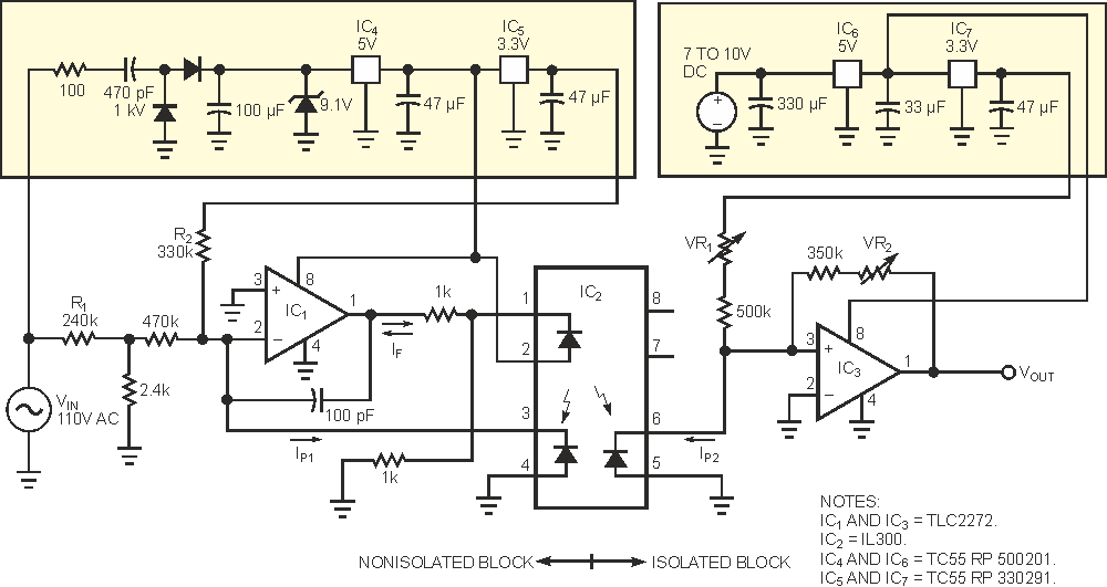
The use of a linear optocoupler and a capacitor-based power supply yields a simple, yet precise power-line-monitoring system. The circuit in Figure 1 converts the 110 V-ac power-line voltage to an ac output voltage centered at 2.5 V, covering 0 to 5 V. The circuit isolates the output signal from the power line. You can connect the output directly to an A/D converter. For other power-line voltages, simply change the value of R1. For a power-line voltage of 220 V ac, use a value of 470 kΩ for R1. The input stage is a nonisolated block that uses the neutral line as a ground reference. This block receives power from a capacitor-based power supply that provides a stabilized 5 V-dc voltage and a 3.3 V dc reference. The TLC2272 op amp, IC1, and the TLC2272 linear optocoupler, IC3, form a feedback amplifier in which the IP1 current is proportional to the input voltage, VIN.
 |
||
| Figure 1. | An isolated optocoupler circuit allows you to make dc measurements of the power-line voltage. | |
Resistor R2 adds a dc offset current to allow for both polarities in VIN. The match between the two photodiodes in the IL300, IC2, ensures that IP2 is closely proportional to IP1. The output stage converts IP2 to a voltage level isolated from the power line. Variable resistor VR2 trims the overall gain, and VR1 adjusts the output-voltage offset, which is nominally 2.5 V. You can test this circuit using simulation the model in Listing 1 for IC2. Typical values for K1 and K2 (optical transfer ratios) are approximately 0.007. The global optical transfer ratio is K3 = K2/K1.
After performing the simulation, you can build and test a prototype. The power supply for the isolated block provides 5 V dc and a 3.3 V reference from an available voltage of 7 to 10 V. You do not need the regulated 5 V if that voltage is already available in your system.
An important goal in this design is to obtain a stable dc voltage at the output. This property is crucial for dc measurements of VIN. Even if you suppose the ac power line to be free of dc voltage, some types of loads drain dc currents, thereby introducing a small dc voltage because of voltage drops in the ac lines. Thermal drifts in the output voltage stem principally from drifts in K3. In tests of the prototype, the K3 temperature coefficient was 470 ppm/°C. Table 1 shows VOUT at different temperatures. The TLC2272 op amp has rail-to-rail output, yielding a wide output-voltage range, and low quiescent current, simplifying the capacitor-based power supply. Because the TLC2272 is a dual device, you can connect the unused half as a voltage follower. When you monitor a three-phase power line, you'd use one and one-half TLC2272s. Note that the op amps in the isolated block, IC3, and the nonisolated block, IC1, cannot be halves of the same chip; otherwise, you'd lose the isolation.
| Table 1. | Output offset-voltage drift | ||||||||||||||||||||||||||||||||||||
|
|||||||||||||||||||||||||||||||||||||
The main specifications of the circuit are
- 5300 V-ac-rms galvanic isolation,
- 0.08% linearity,
- 470-ppm/°C thermal shifts in VOUT,
- 2° phase shift at 50 Hz,
- dc to 1-kHz bandwidth at –3 dB.
 |
||
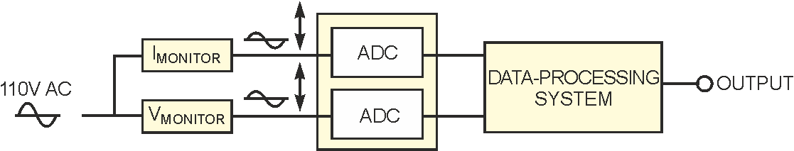
| Figure 2. | By adding two ADCs and a microcontroller, you can measure power-line voltage and current parameters. |
|
If you connect the output to a 10-bit A/D converter, one LSB is equivalent to 0.5 V in the 110 V power line. You can add a Hall-effect sensor to the circuit for current measurements. The LTS series from LEM is suitable for this purpose, because these devices operate from a single 5 V supply and provide a 2.5 V-centered output. Figure 2 shows a system that integrates voltage and current measurements. The processor computes true-rms voltages and currents, apparent and active power, and power factor.