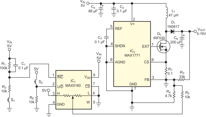
Digitally controlled potentiometers are useful for generating analog control voltages under the control of a microcontroller. In some applications, manual pushbutton switches could replace a microcontroller and simplify product design. Mechanical switches exhibit contact bounce, and, when a user actuates them, they may open and close many times before reaching a stable state. A digital potentiometer's control inputs lack switch-debouncing capabilities, and its up/down control is not suited for pushbutton operation. Figure 1 illustrates solutions to these issues and shows how to use a digital potentiometer to control a boost converter.
 |
||
| Figure 1. | A digital potentiometer, IC1, and two pushbutton switches, S1 and S2, let you adjust the regulated output voltage of boost converter IC2 over a 10 V range. |
|
The potentiometer, IC1, a MAX5160M, presents an end-to-end resistance of 100 kΩ. To increment the wiper's position, W, you press and hold the U/D pushbutton, S2, to pull the U/D pin high and then press and release pushbutton S1 to pulse the INC input. Similarly, you decrement the wiper position by releasing S2 and pulsing S1.
A time-delay network comprising R1, R2, and C1 masks S1’s switch bounce, which would otherwise toggle the wiper's position between VDD and approximately 0 V. When you press S1, capacitor C1 charges via R2 and causes the INC pin to ramp slowly toward 0 V, thereby removing the effects of S1’s contact bounce. The R1C1 time constant requires that you depress S1 for several milliseconds before the INC input takes effect.
In this application, switching converter IC2, a MAX1771, operates as a standard boost converter and increases its 5 V input to a higher voltage positive output. You can use Equation 1 to set IC2’s output to a nominal 12 V output without the digital potentiometer:
 |
(1) |
Connecting IC1’s wiper via 10-kΩ resistor R5 to IC2’s FB (feedback) node sets IC2’s voltage-feedback level. Although inclusion of feedback resistors R3, R4, and R5 and digital potentiometer IC1 complicates the precise calculation of IC2’s output voltage, you can simplify the math by calculating the output voltages at the potentiometer's extreme settings. Thus, with IC1’s wiper set to 0 V, R' equals the paralleled resistance of R4 and R5, and IC2’s maximum output voltage becomes Equation 2:
 |
(2) |
or VMAX = 16.84 V.
With IC1’s wiper set to 5 V, you can attempt to calculate the minimum output voltage by summing voltages into the feedback node:
 |
(3) |
which simplifies to VMIN = 0.48 V. However, Equation 3 provides an incorrect value for VMIN because a boost converter's output voltage cannot go below its input voltage. You can approximate VMIN by substituting a value of 10 kΩ for R5 in Equation 3 and solving for VMIN: VMIN = 4.93 V.