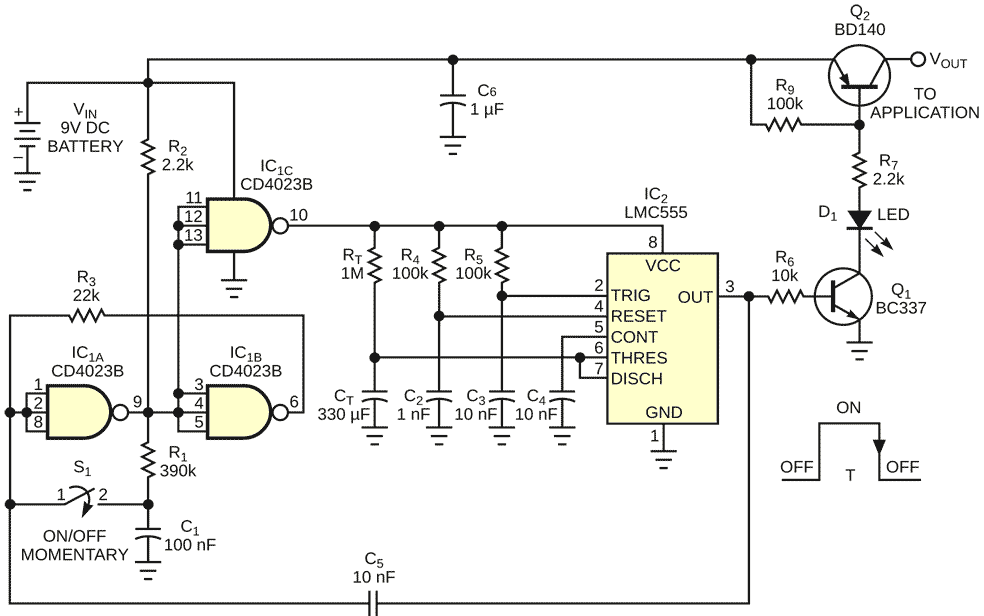
The circuit in Figure 1 provides a simple and inexpensive way to protect one of the most valuable components in portable applications: the battery. Applications include all portable equipment that requires a limited time of operation, such as test instruments, guitar tuners, and electronic toys. Pressing the on/off momentary switch starts the cycle, and the circuit provides power to the application circuit. If you again press the switch at any instant, the circuit switches off and “sleeps” until the next cycle. In case you forget to switch off the circuit, the circuit incorporates an auto-power-off function with a time period that is a function of preprogrammed time constants.
 |
|
| Figure 1. | This battery-saving circuit is handy for applications requiring a limited operating time. |
IC1 and related parts provide a bistable toggle function and also ensure protection against switch-contact bounce. IC1C buffers the toggled signal and isolates the R1-C1 charging current. This signal feeds the IC2 timer, configured as a monostable multivibrator that remains activated until it times out, according to the expression t = 1.1×RTCT. This figure is the auto-power-off time. In the example, this interval is approximately six minutes. The timer’s output feeds the Q1 inverter that activates medium-power, pass-through Q2 transistor. This circuit is configured as a p-n-p block to ensure low losses to the load. The loss comes only from VCE(SAT) – approximately 0.2 V at 100 mA, or 20 mW. For applications demanding more current, you can choose a more suitable transistor. A MOSFET can be an efficient approach when you need either lower standby losses or a lower voltage drop between the battery and the application circuit.
Standby losses in the switched-off state are negligible, because the circuit draws power only from the CMOS gate in the inactive off-state. LED D1 indicates the on-off status of the circuit. No extra power comes from the battery to drive this LED, because it is connected in the current-source leg of the driver transistor. The output transition to 0 V during time-out ensures the timed power-off by means of the C5 feedback loop that toggles the bistable circuit to the off state, performing the same role you might have forgotten with the on/off switch. This simple circuit is useful when the application doesn’t require a microcontroller.