Vintage triggered-sweep oscilloscopes find use in many applications. However, they have no internal delay line, so they can't display the pulse that triggers the sweep. Moreover, early laboratory scopes contain delay lines having insufficient delay to display such pulses during a uniform portion of the sweep. With such oscilloscopes, the true pulse shape remains a mystery. You can circumvent these limitations if you add an external delay line and equalizer. The scope can then display the exact trigger-point trace. The instrument then becomes easier to use, and the measurements become more trustworthy. For every additional microsecond of equalized cable, the scope can display a microsecond of pretrigger information. Figure 1 shows the components you need to implement these improvements on a Philips PM3230 10-MHz oscilloscope. The components are a wideband amplifier to restore the signal to its original level and provide a trigger; a 750-nsec delay cable; and a passive, two-stage equalizer.
 |
|
| Figure 1. | This circuit modifies vintage oscilloscopes having no internal delay line. |
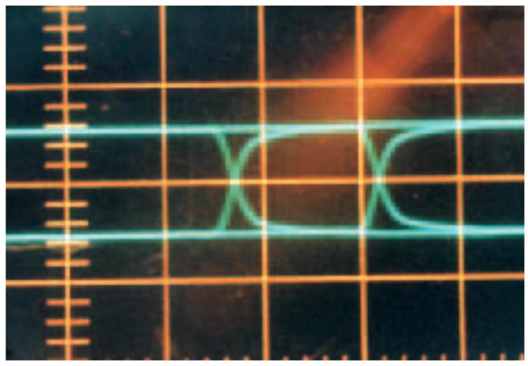
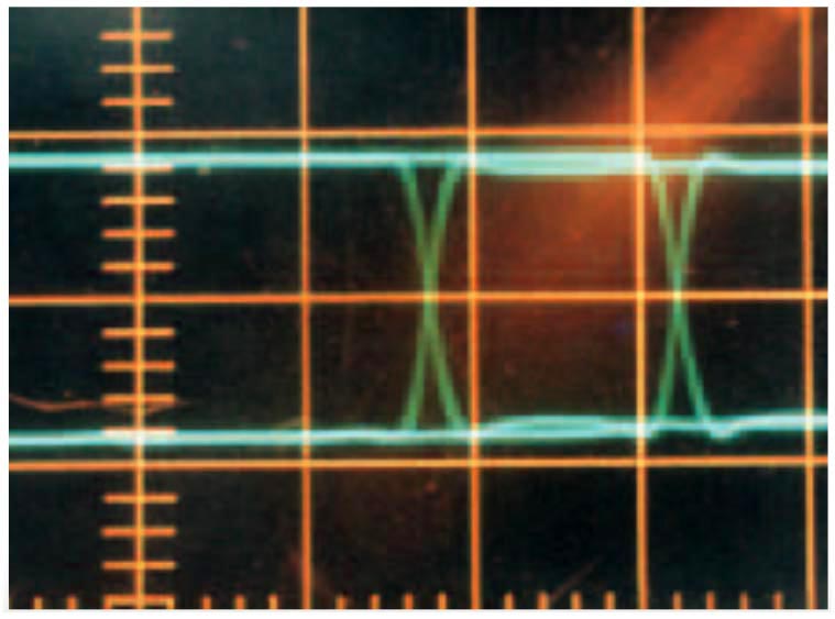
CATV cables, such as RG6U, RG59U, and others, are commonly available at garage sales and second-hand stores. You connect the 75 Ω cables with solid or foam dielectrics using standard CATV connectors to make the 750-nsec delay line. A low-impedance driver displays the bipolar step response of the delay line, as the eye pattern in Figure 2a shows. The delay line transmits approximately 65% of the signal at audio frequencies, because of resistive losses. The losses increase at higher radio frequencies, because of the skin effect in the conductor. The theoretical form for the step response that the skin-effect loss causes is a complementary error function,
(see Reference 1). The time, t, refers to the start of the step after traversing the cable of 160 m length. Computer evaluation of this function shows the constant to be
for best agreement with the step response in Figure 2a. You cannot adequately correct this functional form by using the usual single-bridged-T filter. You therefore apply time-domain methods to obtain the two-stage, pole-zero-cancellation equalizer in Figure 1 (Reference 2). This double-bridged-T filter corrects the cable's phase and amplitude distortion over a 10-MHz band.
|
|||
| Figure 2. | The step response through the 750-nsec cable (a) and the complete network, including the cable (b), differ. |
||
Each of these two filters is basically a resistive attenuator, but fast steps can bypass the attenuation during a time constant, τ. For short times, the equalizer's input port sees a load of only the 75 Ω cable via the capacitor, which presents a short circuit at high frequencies. The inductor presents an open circuit at high frequencies, so the resistors have no effect for short times. Eventually, as t surpasses τ in the step response, the capacitor and inductor yield to the resistive attenuator while presenting the 75 Ω load to the equalizer's input. With only the first, τ = 180-nsec filter, the step response becomes a more finely rounded waveform. With the second, τ = 25-nsec filter, the step response is a sharp step, limited only by the oscilloscope's bandwidth. Each filter resides in a reclaimed CATV signal-splitter box. You can connect these 75 Ω constant-resistance filters at various locations along the delay line without incurring reflections. You can therefore use this arrangement to fine-tune the passive components to eliminate residual reflections, using time-domain reflectometry.
The AD8055-based amplifier has greater-than-100-MHz bandwidth, fully adequate for the 10-MHz oscilloscope. Its input impedance is 1 MΩ in parallel with 30 pF to match the oscilloscope's input and its low-capacitance probes. Figure 2b shows the final eye pattern, using the amplifier, the two-stage equalizer, and the 750-nsec delay cable. This pattern is essentially identical to the eye pattern that ensues using the oscilloscope without the circuit in Figure 1, except for the 750-nsec temporal shift. You can see the benefit of the circuit in Figure 3. Trace A shows the original impulse response of the oscilloscope without the circuit. Trace A is merely an uninteresting, featureless trace. For Trace B, the input impulse passes through the amplifier to the external-trigger input and then through the equalizer and delay cable to the oscilloscope's input. Because its delay is longer than the intrinsic delay of the oscilloscope in starting its sweep, a clean pulse of approximately 20 nsec appears on the display. You can now use the complete unit as a 10-MHz laboratory oscilloscope.
 |
|
| Figure 3. | Traces A and B show the impulse response, respectively, without and with the delay network. |
You can define an input impulse as an even function composed purely of cosine waves of zero phases. However, the cable's impulse response is simply the derivative of the waveform in Figure 2a and acquires a long, slow tail. This impulse response is thus no longer an even function, so its composite cosine waves have evidently acquired various phase shifts accruing to the cable. Figure 3 illustrates that the circuit in Figure 1 corrects these phase shifts and amplitude variations. Trace B shows a short, symmetrical pulse with no tail, an even function as similar as possible to the input impulse using this oscilloscope.
References
- Nahman, NS, “The measurement of baseband pulse rise times of less than 10–9 second,” Proceedings of the IEEE, Volume 55, No. 6, June 1967, pg 855.
- Houtman, Hubert, “1-GHz sampling oscilloscope front-end is easily modified,” Electronic Design, September 2000, pg 176.