When EDN published its first issue in 1956, electrical measuring instruments looked a little different than they do today.
Howard Skolnik, a former colleague and key analog mentor from my Burr-Brown days, has always had a passion for significant products made by pioneering electrical instrument companies and has accumulated a large collection over the years that includes Burr-Brown, General Radio, Leeds, and Northrup and Weston.
Skolnik has been looking for several years for a proper institution to maintain his collection that took 50 years to accumulate, refurbish, and document. He has contacted many institutions including the Smithsonian in Washington, without success, for a variety of reasons. He is hoping that someone will appreciate what this collection represents and can offer help to preserve it.
This slideshow features some items from the collection from around 1956, to give you an idea of what instruments looked like when EDN was born.
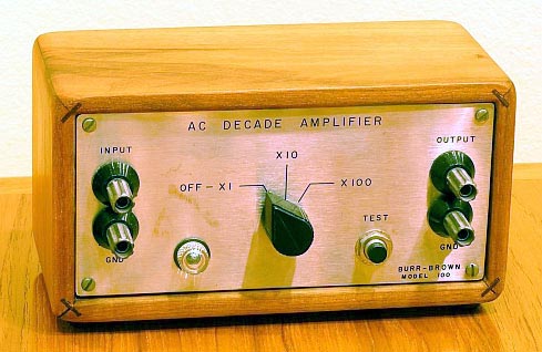
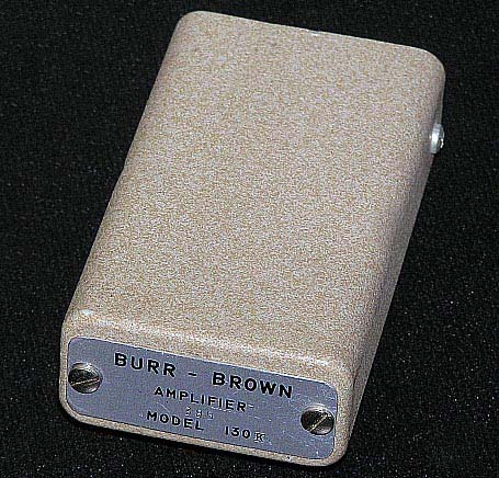
Burr-Brown was incorporated on the same day EDN published its first issue, May 8, 1956. That year Burr-Brown started with “instruments” in wooden boxes. The first product was the Model 100 AC Decade Amplifier. This was not an op-amp. Other early products, in wooden boxes, included a Differential AC Amp, Square Wave generator, Variable Gain Preamp, and AC Millivolt Meter.
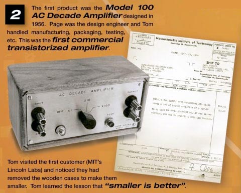
The Model 100 was the first commercial transistorized amplifier, and when co-founder Tom Brown visited customer MIT, he found that they were discarding the boxes to make them smaller.
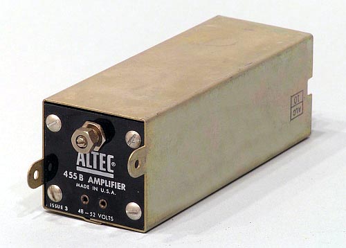
Telephone repeaters made long distance phone service possible between 1900 and 1915. Circa 1959, Altec Lansing developed the first solid-state telephone repeater amplifier shown above.
This Model 455B transistor amplifier telephone repeater datasheet provided installation and maintenance information in addition to specs, and below you can see the schematic for the 453B transistor amplifier.
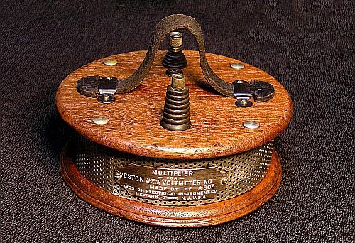
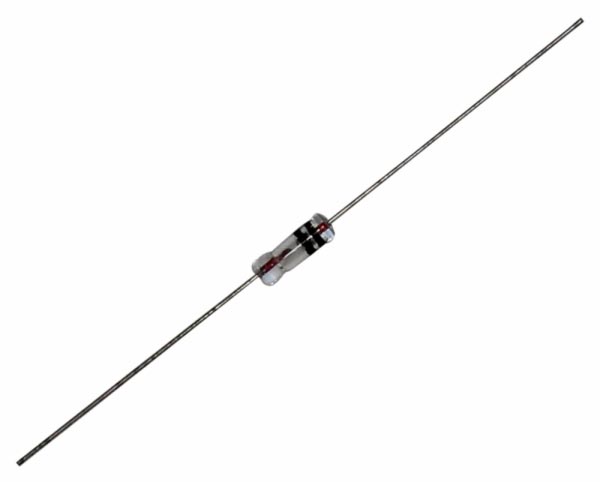
The analog voltmeter back in the 50s had a galvanometer movement with a multiplier resistor (see above, I think a 60k ohm maximum resistance value) in series with it. The potential drop across the galvanometer itself is small, and the value of the multiplier is adjusted to allow most of the potential drop to be measured to take place across it.
A stand-alone meter movement was only able to measure around 0.5 V, so in order to measure larger voltages, a proportioning circuit allowing only a precise part of the measured voltage to drop across the meter movement must be created. This will extend the meter movement's range to higher voltages.
The design used to create such a circuit was a voltage divider used to proportion the total measured voltage into a lesser fraction across the meter movement's connection points. Since the voltage divider circuits are built from series resistances, a resistor inserted in series with the meter movement was used (using the movement's own internal resistance as the second resistance in the divider).
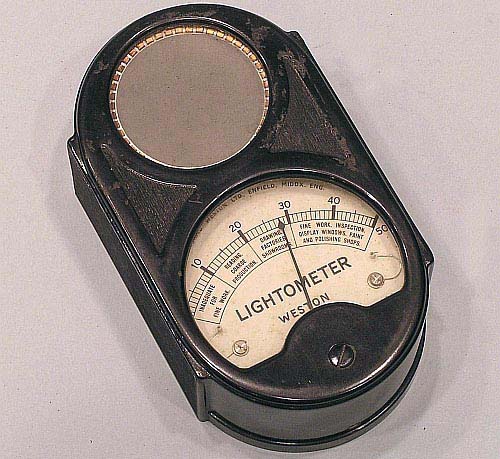
A Weston Model E703 Lightometer was used for general light intensity and not photography. It read light values (foot candles) but there is no mechanism to convert them to exposure settings for cameras using shutter speeds, apertures, and file speeds. It measured 4 5/8" high by 2 5/8" wide with a depth of 1 7/16" and weighed in at 12 ounces. In the UK, where it was made, it was sold with a leather case for £3, 7 shillings, and six pence. That's just under £3.40!
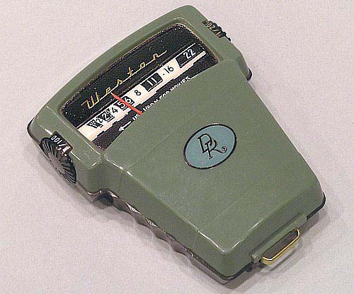
This Weston Direct Reading Exposure Meter, Model 854, from 1956 was a "direct reading" meter for the amateur photographer. Easy to use, just point and read the exposure. It used a revolving plate that partially covers a selenium cell on the back of the device so that the user would need to hold it upright at eye-level. This calibrated the meter for the film speed used by the photographer. To get a faster speed, you would uncover more of the cell, which allowed for a higher reading. It had a knob on its side that the user would turn to get a desired shutter speed. The amateur photographer could then read the proper aperture. Alternately, they could rotate the knob until a desired aperture is found and then read the resulting shutter speed.
It was designed to be used with one hand, so the user would grip the bottom portion contoured on the sides and use the thumb to rotate the knob. The design was made so that one could use the left or right hand to roll knobs on either side.
Limitations became a problem as higher speed films like 400 and 500 ASA were being introduced since this device could only be used up to Exposure Index (E.I.) settings of ASA 250.
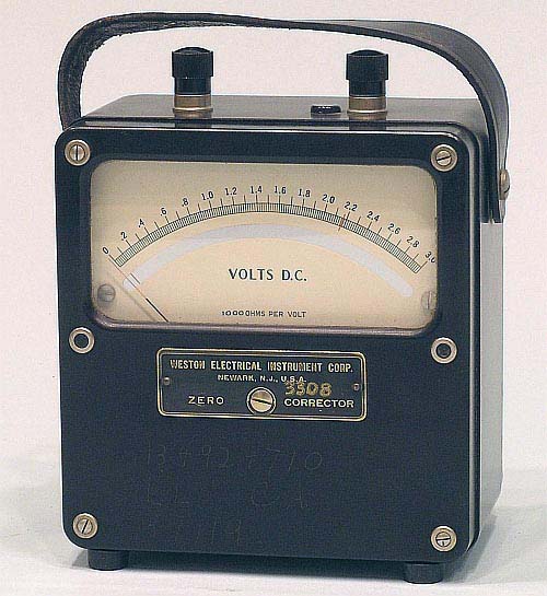
The Weston Model 931 DC Voltmeter from 1956 ranged to 3 V DC at 10,000 ohms per volt. It was a 1% core magnet moving coil type of design with an accuracy within ½ of 1% in a bakelite case. Other meters in this series were DC Ammeters, milliammeters and microammeters in the same case and configuration.
The first modular solid-state op amp was developed by Burr-Brown Research in 1958. It had Germanium transistors in the design.
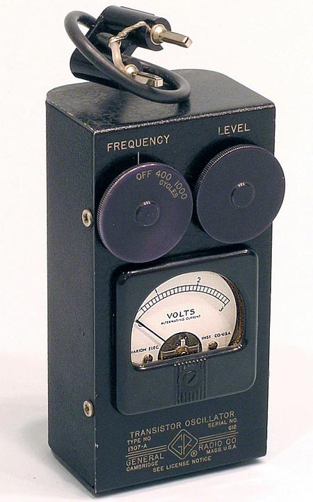
This General Radio Model 1307-A Transistor Oscillator was a pocket-sized signal source which operated from frequency outputs of 400 cps to 1,000 cps (Hertz for those of us in the 21st century). It was used as a power source for the 1552-B Sound Level Calibrator or the Type 546-C Audio Frequency Microvoltmeter. It was frequently also used for continuity checking audio systems to help set operating levels, check sensitivity of oscillographs, doing preliminary calibration of electronic systems, and as a power source for bridge measurements at 400 cps to 1,000 cps.
The electronics design used a PNP transistor that was connected to a Hartley oscillator, using a 2N1372 Germanium transistor or equivalent. The round frequency switch shown on the front panel of the 1307 could be set at 400 cps where the internal circuit tuning inductor entire winding was accessed. When set to the 1,000 cps position, a tapped position on the tuning inductor was used.
An extra winding on the tuning inductor was used as the output load. A rectifier-type voltmeter connected across this winding would indicate the voltage at the output terminals. A Germanium rectifier biasing circuit, 1N34-A, was used to ensure proper starting of the oscillator over the entire wide temperature range.
The device was battery operated using three Type RM-1 cells in series.