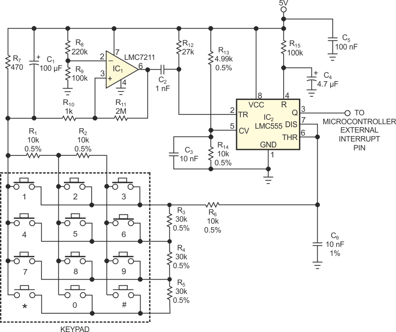
In most keypads, pressing a key closes a contact that bridges two lines in an xy matrix. If you use a microcontroller to detect a key closure, checking the states of (x+y) lines requires an equal number of I/O pins. Occupying only one free I/O pin, the circuit Figure 1 communicates with a microcontroller by generating a single pulse each time someone presses a key. The pulse's width is proportional to the number of the pressed key, and the microcontroller identifies the pressed key by measuring the pulse's width.
 |
|
| Figure 1. | Two ICs form a pulse-width-modulated keypad interface that uses only one microcontroller-input pin. |
IC2, a CMOS LMC555 version of the popular 555 timer, operates as a monostable one-shot multivibrator. In the circuit's resting state, a transistor internal to IC2 at Pin 7 shunts C6, and IC2’s output at Pin 3 remains at logic low. Pressing any key on the keypad connects two resistors from two groups – R1 and R2 in one group and R3, R4, and R5 in the other – in series with R6. The sum of the two resistors varies in 10-kΩ increments, and the total resistance is proportional to the number of the pressed key.
Pressing any key draws current through R6, R7, and the selected keypad resistors and raises the voltage at IC2’s Pin 7. After C1 charges, introducing a short delay that's sufficient to eliminate keypad-switch contact-closure bounce, CMOS comparator IC1 detects the small voltage drop established across R7. The output of IC1 (Pin 6) goes from 5 to 0 V, which in turn triggers Pin 2 of IC2. Timer IC2’s output (Pin 3) goes high and begins to charge capacitor C6 at a time constant that depends on the selected key. When the voltage across C6 reaches two-thirds of VCC, or 3.333 V, Pin 3 goes low and discharges C6. The following equation calculates IC2’s output pulse width, T:
T = 1.1 × RS × C6,
where RS equals the sum of the selected keypad resistors and ranges from 10 to 120 kΩ. The pulse width spans a range of 110 to 1320 µsec in increments of 110 µsec.
The smallest relative change in pulse width occurs at the longest pulse ratio, 110/1320, or 8.33%. This ratio provides sufficient margin to allow use of standard ±1% tolerance or better components for those in Figure 1 that are ±0.5 and ±1%. Resistors R13 and R14 compensate for variations in IC2’s internal voltage dividers by forcing the voltage at Pin 5 to two-thirds of power-supply voltage VCC.
The keypad circuit's output pulse drives the external interrupt input, RA2, of a Microchip PIC16F630 microcontroller. An interrupt routine for the PIC16F630 measures the pulse width, verifies that its tolerance is within ±40 µsec, and returns a numerical value of 1 to 12 that corresponds to the pressed key. As a safeguard against erroneous data, the routine returns an error code if the pulse width falls outside certain limits.