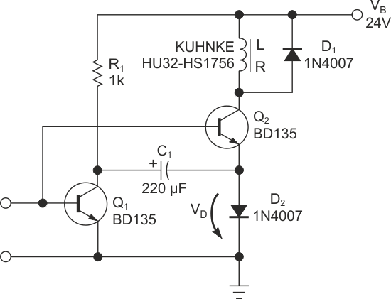
The circuit in this Design Idea bootstraps a large capacitor in series with the solenoid to provide a large actuation voltage (Figure 1). This higher voltage provides substantially more current to operate the solenoid, speeding the operation of the solenoid. You can also choose operating voltages or solenoid specifications that result in lower continuous current through the solenoid, reducing dc power consumption and resulting in a cooler-running solenoid with better reliability.
 |
|
| Figure 1. | This circuit bootstraps the power supply voltage across the solenoid to temporarily double the actuation voltage. |
When there is a 0 V input to the circuit, both transistors are off. Resistor R1 slowly charges the left side of capacitor C1 to the 24 V power-supply voltage. D2 clamps the right side of capacitor C1 to 0.6 V. When the input signal goes high, both the Q1 and the Q2 transistors turn on. This action quickly drives the left side of C1 to ground. Because voltage cannot change instantaneously across a capacitor, the right side of C1 goes down to –23.4 V. D2 steers the solenoid current into the capacitor until it discharges, at which time the solenoid current conducts through D2 to ground. D1 prevents a voltage-overshoot spike when the circuit turns off, and current suddenly stops flowing in D1. It clamps the bottom leg of the solenoid to 24.6 V until the current decays in the solenoid.
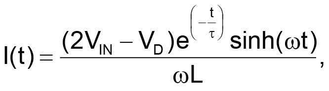
The time constant of the circuit depends on the inductance of the solenoid and the value you choose for the capacitor, which you can calculate with the following equations:

and
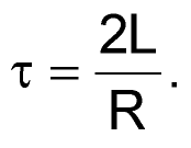
In these equations, e is the mathematical constant, ω is the radian angular frequency, and t is time in seconds. In addition, L is inductance and R is resistance.