The circuit in this Design Idea anticipates, or jumps instantly to, the final voltage of an input-signal change. It relies on the fact that the intended input signal changes exponentially with a known time constant. This circuit was adapted from a 1970s-era instant-reading electronic thermometer, which displayed a patient’s body temperature within seconds after a thermometer probe was placed under the patient’s tongue. It exploits the fact that the temperature probe’s exponential thermal response-time characteristic is known.
 |
|
| Figure 1. | The output of this anticipator circuit instantly jumps to the final voltage of an exponential input signal. |
The circuit uses a quad rail-to-rail amplifier to perform a mathematical operation (Figure 1). The input to the circuit is at Node X. At that node, a filter with a 500-msec RC time constant averages a 1-kHz PWM (pulse-width-modulated) signal. The desired output is a dc voltage proportional to the PWM duty cycle. A long time constant is required to reduce ripple. You obtain an instant output response by differentiating this input signal with the same time constant. The input signal is the voltage on capacitor С1 as it moves from initial voltage VI to final voltage VF. R1 and C1, set the time constant, as the following equation shows:
where e is an irrational constant approximately equal to 2.718281828. You then buffer this signal with an inverting gain of one-half to prevent clipping. Ignoring dc biasing for clarity, the ac output at Node VB is a function of the RC time constant, as the following equation shows:
You then differentiate the inverted signal with amplifier IC1. You set the differentiator time constant with R2 and C2. The gain of a differentiator circuit increases with frequency, making these circuits prone to instability. You use R5 and C8 to keep the circuit stable. At the low frequencies of interest, R2 and C2 dictate the function of the circuit, as the following equation shows:
R1 and C1 set the time constant of the input, so you can match it by making the differentiator time constant, R2•C2, the same. This step cancels terms in the equation and simplifies the expression for output voltage, as the following equation shows:
Due to scaling to prevent clipping, you sum this signal with the input signal in a weighted manner and present this voltage at the positive input of IC4, as the following equation shows.
Note that the first and last terms of the preceding equation cancel out. You then set a gain of three for amplifier IC4, as the following equation shows:
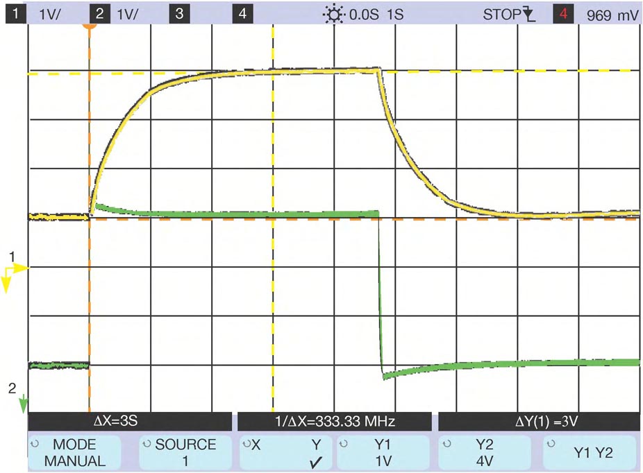
When the input starts to move with a known exponential rate, the output anticipates the result and jumps instantly to what will be the final voltage (Figure 2). You can use this circuit in many applications that have a fixed input time constant.
 |
|
| Figure 2. | The anticipator circuit speeds the response of a slow exponential waveform (yellow) and results in nearly instant response to the final value, with only a small amount of overshoot (green). |