AGC (automatic-gain-control) amplifiers use the nonlinear characteristics of control devices. The magnitude of the real component in some of their differential parameters changes depending on variations in their dc operating points. A typical example is the VA characteristic of a silicon PN junction, which results in the differential conductance directly proportional to the passing dc current (Reference 1). In this form of control, the main problem is the control element's nonlinear transfer characteristic, which causes a relatively large degree of nonlinear signal distortion once the processed voltage amplitude exceeds millivolts (Reference 2).
A photoresistor, which has a VA characteristic that's linear in a large range of voltages, is up to the task. Common photoresistors remain perfectly linear for signal amplitudes of 100 V or more. Therefore, the amplification-control device can be an optocoupler whose controlled element is a photoresistor. The circuit in this Design Idea uses a radiation source whose spectral characteristic fits the spectral characteristic of the photoresistor, and its radiated power should, if possible, be a linear function of the drive signal. Such optocouplers are commercially available, but few have properties good enough for this purpose. Common photo-resistors have spectral characteristics close to the spectral characteristics of the human eye, whose peak sensitivity has approximately a 500-nm wavelength. So a white or green LED (light-emitting diode) is a good alternative. To obtain the highest possible sensitivity, this circuit uses a white HB (high-brightness) LED.
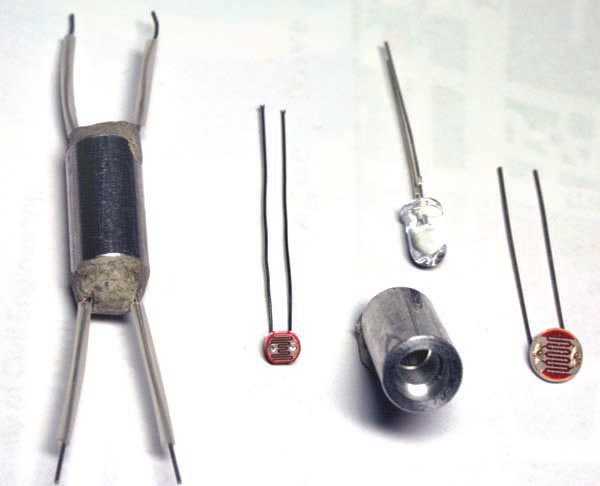
Figure 1 shows the individual components of the optocoupler and the assembled device. The optocoupler comprises a cylindrical holder that accepts a standard 5-mm HB LED from one end and a photoresistor at the other end. An opaque nonconductive seal prevents external light from entering the device. The polished metallic inner wall of the holder results in minimum light loss between the LED and the photoresistor. Available off-the-shelf photoresistors include the NSL-19M51, and a standard white, 5-mm HB LED type L-53MWC*E, with output-light flux of 2500 mcd at a 20-mA drive current.
 |
|
| Figure 1. | A metal tube with an HB LED and a photoresistor forms the optocoupler (left). |
Figure 2 shows the transfer function of the optocoupler using the NSL-19M51 photoresistor. The output resistance of the device can vary from 100 Ω to 10 MΩ with LED-drive currents from 34 mA to 0.1 μA, respectively. The photoresistor's linear VA characteristic, even for large-amplitude signals, lets you use it as the control element even in situations that require a relatively large signal voltage, such as when the photoresistor is part of the feedback loop of an operational amplifier. Figure 2 also shows that you can obtain a variation of linear output resistance over at least five decades with a maximum LED-drive current within the limits of permitted output current of common monolithic operational amplifiers.
 |
|
| Figure 2. | The optocoupler’s logarithmic response in a feedback loop produces a linear amplifier response. |
Such an amplifier can control the overall amplification of the system in the same range without additional current amplification. Due to the photoresistor's linearity, the resulting degree of processed signal nonlinear distortion is almost solely due to the nonlinearity of the operational amplifier. Within the normal operating range, the overall linearity of the system improves with increasing input-signal amplitude because the amount of negative feedback increases with increasing signal amplitude.
Figure 3 shows the amplifier system. The basic signal-processing device is inverting op amp A1. Its inverting connection lets you set the absolute value of the overall amplification from input to output to a value smaller than unity, permitting correct processing of an input-signal amplitude even larger than the regulated output value. Optocoupler IC1 is the core component of the system, whose output, the photoresistor, serves as a variable part of A1’s negative-feedback network. At no-signal conditions, the LED does not illuminate the photoresistor. Thus, its resistance rises to a high value, which can cause dc runaway and the loss of the quiescent operating point of A1. Such a condition is not harmful in principle because the signal path is ac-coupled, preventing the dc error value from getting any further. When a nonzero signal suddenly appears at the input, however, A1’s open-loop amplification would amplify it, causing a rapid rise in LED current. This action would drop the optocoupler's output resistance almost stepwise to a value sufficient to restore the dc operating point of A1. The ac coupling transfers this transient to the output, and it may cause problems in signal-processing circuits following the adaptive amplifier. To prevent this effect, you should limit the maximum value of the feedback resistance to a reasonable value, such as 47 MΩ, the value of R6. Because the op amps have JFET inputs, the value of R6 can be rather high. The value of 47 MΩ is a reasonable compromise, limiting the maximum absolute value of voltage amplification in A1 to approximately 82 dB. The limiting factors for selecting a value for R6 are the noise and the open-loop amplification of A1.
 |
|
| Figure 3. | The adaptive-amplifier system has the optocoupler in a feedback loop. |
Buffer A2 separates the nonlinear load through the rectifying diodes from the output signal, thus preventing the nonlinear load from the rectifying diodes from distorting the output signal. Diodes D3 and D4 compensate the threshold voltage, including its temperature coefficient, of rectifying diodes D1 and D2. If you do not need to set the regulated output-voltage amplitude to a value smaller than the threshold value that the bias current in R4 sets, you can replace D3 and D4 with a short circuit and omit R7. You can set a larger-than-unity voltage amplification in A2 to obtain a regulated output amplitude lower than the threshold that the bias in R4 sets. Just insert an additional resistance in series with the D3/D4 pair.
The rectifier uses Schottky diodes, which have a lower threshold voltage than conventional PN diodes. They also have a short recovery time, keeping the same rectification efficiency at high signal frequencies. The rectifier operates as a full-wave voltage doubler, providing peak-to-peak rectification even for signals with nonsymmetrical waveforms. The rectifier output feeds to A3, a voltage-to-current converter, which drives the LED in the optocoupler. A rectification threshold-shifting bias-current source connects to current-sensing resistor R4. In this case R5 simulates a current source, setting the regulated output-voltage amplitude. If the 15 V supply voltage isn't perfectly stable, obtain bias current from a separate stable source. An opposite-polarity diode connects across the optocoupler's input to protect the LED from reverse polarization at no-signal conditions.
This LED current-control circuit has an important advantage: It permits an almost-independent adjustment of the attack and release time. You can adjust the attack time through variable resistor P1, using a higher value if necessary. You can also adjust the release time using P2. The photoresistors used have a rather good response speed, and the introduced delay at a stepwise illumination variation is acceptable for most practical requirements.
Figure 4 shows the overall response of the adaptive amplifier system. The output signal remains constant at 350 mV rms ±1 dB for input-signal voltages of less than 70 μV rms to more than 1.2 V rms-that is, over a more-than-85-dB range. The no-signal output noise is less than 6 mV rms, yielding an SNR (signal-to-noise ratio), or processed-signal dynamic range, better than 20 dB at the onset of regulation in the worst-case condition and improving proportionally with increasing input-signal level.
The key parameter this design follows is its linearity. Because of the photoresistor's linearity and the separation of the nonlinear rectifier load from the output, the gain control introduces negligible nonlinearity. Thus, A1 alone, in principle, determines the overall linearity of the system.
 |
|
| Figure 4. | The amplifier system has a constant output from 0.1 mV to 1 V-rms input. |
Harmonic analysis of the output signal at 1 kHz yields higher harmonics with amplitudes lower than A1’s noise level for all input voltages to 200 μV rms and below –75 dB for input voltages to 1.5 V rms. The nonlinear distortion becomes noticeable only at large input amplitudes exceeding the regulation range of the system, raising the second harmonic to –45 dB and the third harmonic to –40 dB at 2.5 V-rms input.
Within the AGC's range limits, the overall transfer linearity improves with increasing input-signal amplitude due to the increasing degree of negative feedback to A1 at increasing input-signal amplitudes. With a value of 10 kΩ for P1 and 1 MΩ for P2 and a stepwise input-signal variation between 100 μV and 50 mV rms, the attack and release times are approximately 0.2 and 2 seconds, respectively. The recovery time from a 1-kHz-more than 10 V-rms input overdrive-to full no-signal sensitivity is less than 2 minutes. You can adjust all of these time intervals in a wide range by varying the values of C4, C5, P1, and P2, with P1 setting the attack time and P2 setting the release time.
References
- Foit, Julius, “AGC amplifier features 60-dB dynamic range”
- Foit, Julius, “Logarithmic Processing Amplifier,” Proceedings of the Fifth WSEAS International Conference on Microelectronics, Nanoelectronics, Optoelectronics, March 2006, pg 6.