There are many circuits of soldering station controllers, but absolutely all close the temperature feedback loop using the soldering iron heater thermistor. The performances of the soldering station can be improved and the circuit can be made simpler if the heater is also included in the feedback circuit.
In the manufacture of a ceramic heating element of a soldering iron (for example, take A1321 – 24 V/50 W), a thermistor and a heater are formed in a single technological cycle. It can be assumed that their temperature coefficients are also the same. Direct measurement confirms this.
An improved version of the well-known controller circuit based on two comparators is proposed (Figure 1). A heater (Rh) and a thermistor (Rt) are connected in series in the feedback circuit. The resistance Rh is approximately 10% of Rt and should not, it seems, greatly affect the switching threshold of the comparator. But this is only at first glance. When turned on, the heater heats up to a cherry color, which indicates its temperature approaching 800 °C, and maybe even higher. In this case, the resistance can exceed the initial one by 4-5 times, i.e. it is already about 20% of the total. The thermistor located at a distance and in contact with the colder soldering iron tip is heated much less.
 |
|
| Figure 1. | The scheme of an analog soldering iron controller. |
The elementary conclusion is that the heater as a temperature sensor makes a sufficient contribution to the overall picture, especially when the soldering iron is operating at high temperatures. Indirect evidence is the fact that the time to reach the 360 °C line at a “cold” start in the proposed scheme is almost 10 s longer and amounts to 60 s. If desired, it is easy to check by connecting the upper Rt pin according to the scheme to the positive supply rail. The stronger the heating, the earlier the circuit turns it off, while maintaining the set tip temperature. Do not forget that due to the spatial separation of the sensor and the heater, a time delay in the feedback loop is inevitable, during which the temperature of the heater will significantly exceed the operating temperature by the time the comparator is triggered. Perhaps the proposed solution, in addition to its elegance, by limiting the maximum temperature of the heating element, will extend the life of the soldering iron, slightly "dulling" the reaction time.
 |
|
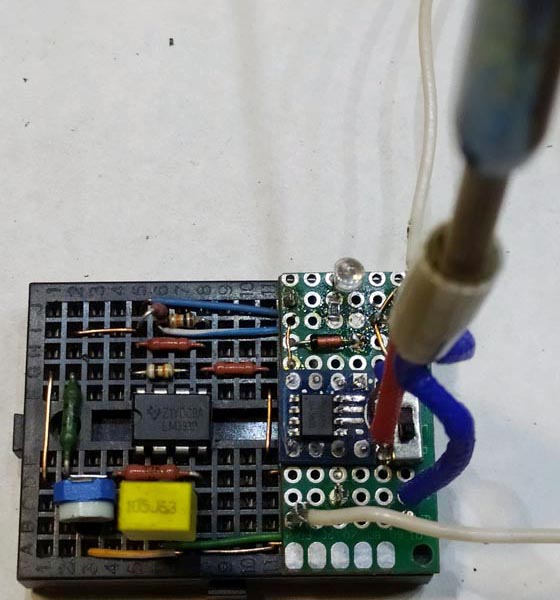
| Figure 2. | Prototype of a soldering iron controller on a breadboard. |
At the specified values, the controller allows you to adjust and stabilize the temperature of the soldering iron tip with an accuracy of ± 2 °C in the range from 150 to 450 °C. The control characteristic of the potentiometer R2 must be linear. The rated power dissipation of the resistor R4 is at least 0.25 W. The circuit is operable in a wide range of supply voltages, provided that the values of resistors R1-R4 are adjusted. To indicate the mode, a blue LED can be connected in parallel with the heater. The appearance of the controller prototype is shown in Figure 2.