One of the effective passive means you can use to suppress the ringing and clamp the overvoltages caused by the leakage energy in a flyback transformer is to implement a recuperating winding bifilar with the primary winding. This is the same technique commonly used to demagnetize the transformer in a forward converter topology. Indeed, this winding is tightly magnetically coupled with the primary winding, but after steering the leakage energy back to the power input, technically it is still a secondary winding. Therefore, it also can be used for other purposes, for example to self-supply a PWM controller or an embedded converter.
Figure 1 shows a flyback converter with an additional recuperating and self-supplying winding, NR, wound bifilar with the primary winding, NP, implemented on a modified demonstration board of the Viper17L from STMicroelectronics [1]. NS is the secondary winding, and the residual leakage inductance is represented by LLK. RS1 is a current sense resistor, and R1 is a current-limiting resistor. Transformer ratios are the same as in the original transformer.
 |
|
| Figure 1. | A bifilar demagnetizing winding added to a flyback transformer shunts the power switch output capacitance, COSS; steers the leakage energy back to the supply rail; and clamps the switch voltage during the turn-off transition. Then, switched to the supply pin of a converter, this winding works as a self-supply winding. |
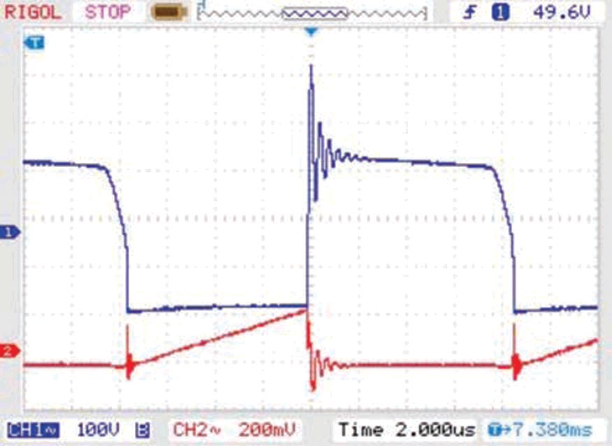
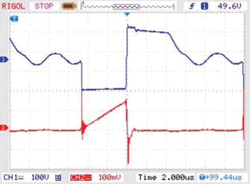
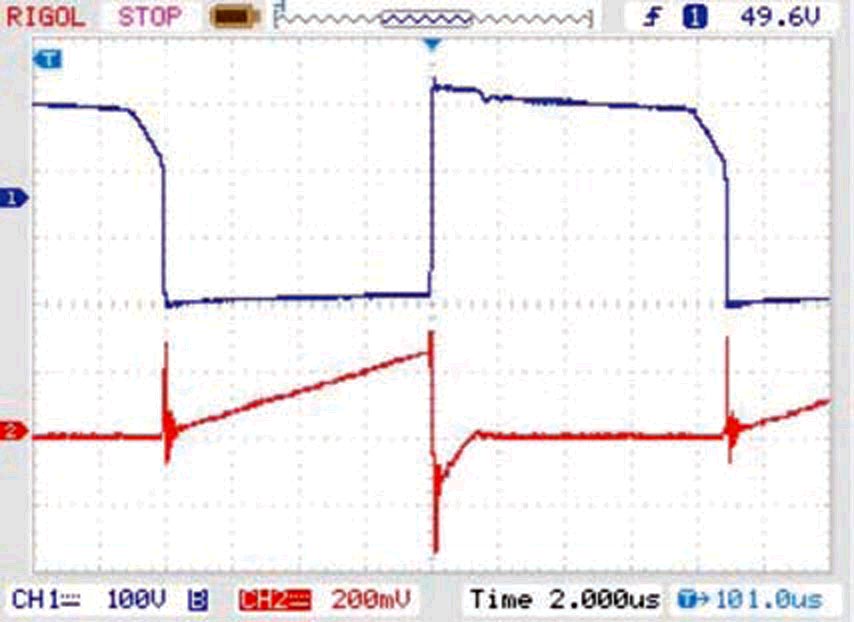
The output voltage is slightly lowered (11.5 V) from the original 12 V to accommodate a power supply rail down to 145 V DC. Figure 2a shows the power switch voltage and primary current waveforms of the original Viper17L configuration with the snubber disconnected. You can see that the ringing due to the leakage inductance is around 540 V peak at 160 V DC power-supply line at full load (500 mA). Figures 2b and 2c show the same waveforms when the recuperating bifilar winding is implemented as a snubber and a self-supply winding. When the supply rail voltage is first applied, the high voltage current generator implemented in the Viper17 starts charging capacitor C4 until the VDD start-up threshold of the converter is reached and the PWM control is activated. The converter is then powered by the energy stored in capacitor C4. During the on phase, all diodes, D2, D3, and D4, are reversed biased. When the power switch turns off, the magnetizing current flows in the recuperating winding, forcing D3 to conduct and thus limiting VDS to 2×V DC. When the leakage energy is fully returned to the power input, D3 is reversed biased and the recuperating winding starts recharging capacitor C4 through diode D2. Charging current cannot flow from the power rail as D3 is biased off, and thus the recuperating winding is supplying the converter.
|
|||||
| Figure 2. | With the snubber disconnected, ringing occurs at the power switch voltage (Channel 1, blue) and primary current (Channel 2, red) waveforms when the converter is without the recuperating winding at full load (a). Shown are waveforms with the recuperating winding at light load, 100 mA (b), and full load, 500 mA (c). When in burst mode, the switching frequency is lowered to about 1 kHz (Channel 1), and the regulation is maintained by keeping the feedback voltage, pin 4 (Channel 2), within the burst- mode threshold levels (d). |
||||
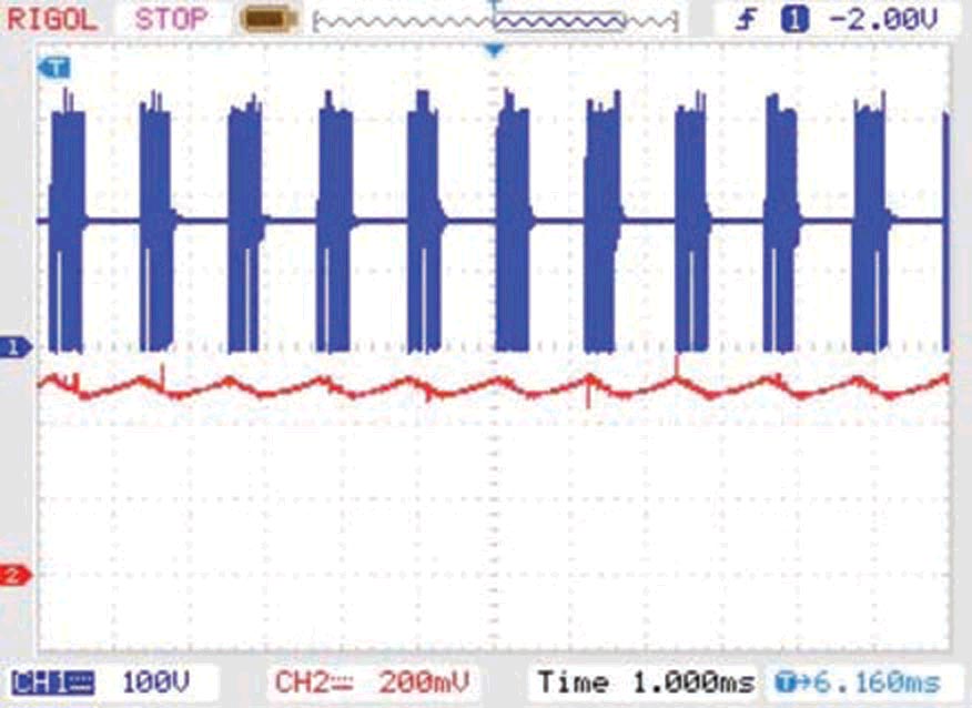
The Viper17 is efficiently designed for low standby power consumption by entering burst-mode operation at no load, switching the internal circuitry to low power consumption when idling, and so on. To preserve the burst mode of operation, a preload resistor, R2, of 1 kΩ is included, thus lowering the average switching frequency at no load, as seen in Figure 2d. In this way, the bifilar recuperating winding successfully sustains the operation of the converter at any load conditions and, at the same time, effectively clamps the overvoltages on the power switch caused by the leakage inductance of the flyback transformer.