Passive current shunts for measuring the value of current flowing through a relatively small-value resistor often have a full-scale voltage drop of 60 mV for higher-power equipment and 200 mV for electronic instruments. Similarly, simple current-to-voltage converters, in which the measured current flows through a sensing resistor, often have even higher voltage drops. In some cases, however, the voltage drop between the input terminal and the ground must be as low as possible; 0 V – independent of the value of measured current – is ideal. If your application requires this feature, you can use the current-to-voltage converter in Figure 1. In this circuit, resistor R1 serves as a classic current-sensing resistor, on which the instrumentation amplifier senses the measured current, resulting in the voltage drop. The instrumentation amplifier, along with R1, not only serves as an inverting current-to-voltage converter, but also creates a voltage through a resistive network at Point B.
This voltage is equal in magnitude to a voltage drop on R1 and has the opposite polarity to ΔVR1. The net result is that the value of voltage at Input A is theoretically 0 V, regardless of the magnitude and polarity of the current flowing into the input.
 |
|
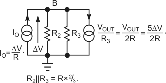
| Figure 2. | The value of R3 is two times that of R2 for a 0 V drop at Input A in Figure 1. |
The design uses the Analog Devices AD8223 instrumentation amplifier because it has a default voltage gain of five; this value remains close to the ideal one with high precision. The typical gain error at the default value of gain is 0.03%, and the worst-case error is 0.1% for the B-grade IC. For gain of five and R1 and R2 having the same value, you can derive that the value of R3 is two times that of R2 for a 0 V drop at Input A (Figure 2). Resistors R1, R2, and R3 in Figure 1 should be high-precision, low-temperature-coefficient types. In the experimental circuit with a value of 20 Ω for R1 and R2, there is an input-referred-current zero shift of 0.8 µA, and the voltage drop at Input A varies by 0.27 mV at a 1-mA input current. Similar slope of negative-voltage variations occurs at Input A for negative-input current. The transfer constant, or transresistance, of the circuit is:

Thus, for instance, an input current of 1 mA causes the voltage of –100 mV to appear at the output. Because the output-current capability of the AD8223 is approximately 2.5 times higher for sinking output current than for sourcing current, the input scale can be higher for positive currents by a factor of 2.5. You can further increase the scales for both positive and negative currents by increasing the supply voltages from ±5 V to ±12 V; you can also use 12 V and –5 V. If your design requires an even higher input current, place a precision voltage buffer, having appropriately high output-current capability, between the output of the instrumentation amplifier and resistor R3.
