Wireless connectivity is a growing trend in portable consumer gadgets. Unfortunately, designs cannot achieve true mobility because of short battery life, so the power cord still must connect the device to the power grid to get the required energy or to recharge the batteries. However, thanks to the low-power requirements of today’s electronic devices, it is feasible to power them wirelessly. This Design Idea describes a simple approach to wirelessly transmitting energy to low-power devices at distances as great as 10 cm. This design uses the resonant-inductive-coupling principle working at 13.56 MHz. The system comprises the RF-power transmitter and the RF-power receiver.
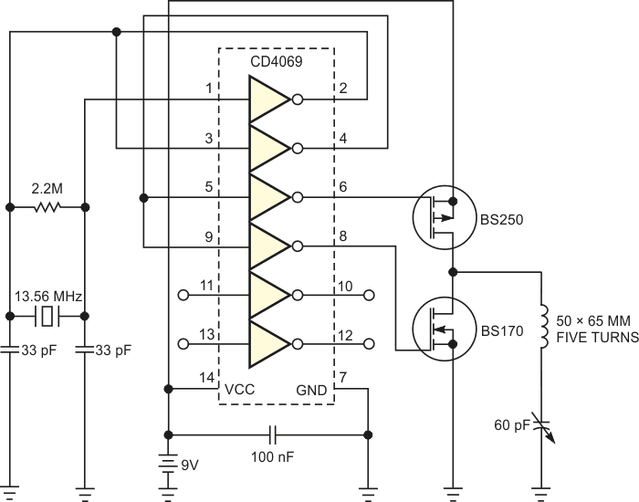
Figure 1 shows the transmitter circuit, which incorporates a 13.56-MHz oscillator. The oscillator encompasses a CMOS CD4069 inverter using power from a 9 V battery to get a wide voltage swing. The oscillating signal then passes through a push-pull output stage comprising two small-signal MOSFETs to get enough current in the output coil. Finally, the output signal broadcasts to the outside by means of a serial-resonant-LC circuit incorporating a coil and a 60-pF variable capacitor tuned to 13.56 MHz.
 |
|
| Figure 1. | A simple 13.56-MHz oscillator energizes an antenna coil, broadcasting power to the receiving circuit in Figure 2. |
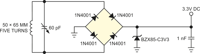
Figure 2 shows the receiver circuit, which comprises an LC network tuned to a carrier frequency of 13.56 MHz. It includes a coil and a 60-pF variable capacitor in parallel with the coil. A full-bridge rectifier comprising four 1N4001 diodes rectifies RF power.
 |
|
| Figure 2. | This receiver rectifies the signal from the oscillator in Figure 1, powering low-current consumer gadgets. |
Rectification efficiency is approximately 50%. Reaching 3.3 V of output voltage requires a 9 V p-p ac voltage across the coil’s pins. A shunt regulator incorporating a 3.3 V zener diode provides voltage clamping beyond 3.3 V to prevent power-level variations with distance. Finally, a 1-nF capacitor after the full-bridge rectifier decouples the power supply. The two coil antennas use five turns of 1-mm enameled-copper wire in a rectangular, 50×60 mm shape.
As an improvement, if your application requires greater distance, you can increase the power supply to 15 V to get a greater voltage swing on the transmitter coil, thanks to the CMOS technology the oscillator design employs. In addition, designing a larger-coil antenna in the transmitter and the receiver sides helps to increase the distance of operation.