Recently, I’ve been working on a solar off-grid monitoring system. In the system are a few split-core Hall effect sensors to monitor DC current in the solar panel current, the battery charge current, and the inverter input current. These currents can vary from 0 A up to about 20 A, so one of the tasks is to calibrate the sensors by checking the sensor’s output at various currents, and with this information, adjust the zero and gain with potentiometers on the sensors.
A little background first: a split-core Hall effect sensor is not a transformer-based sensor (as this would obviously not work on a DC system) but uses a solid-state device to measure magnetic field strength. So, to begin the calibration task, I connected a wire to a bench power supply; one end to the + output and the other end to the – output. Next, I set the power supply to deliver a constant current of 1 A. (This can be done on most power supplies by setting the voltage output to an arbitrary, non-zero, number, say 2 V. Then the current limit is set to 1 A. Some supplies refer to this as the constant current setting.) Last, I opened the split core hinged top, put the wire in and closed the core shut.
Hall effect sensors typically have 3 leads: operating voltage (usually +5 V), ground, and the sensor output voltage which is a linear function of the sensed magnetic field. So now I could measure the output at 1 A, but I wanted to check a few points up to 20 A. I don’t have a 20 A constant voltage power supply. (You’re probably way ahead of me now.) The answer is to open the split core hinge and add more wraps using the same wire. The sensed magnetic field then grows proportionally to the number of wraps. Therefore, to get a 20 A signal, I could put 20 wraps and connect it to the 1 A input or use 10 wraps and a 2 A input. Turns out wrapping and unwrapping is tiring and prone to error and I thought it would be better to set up a calibration station.
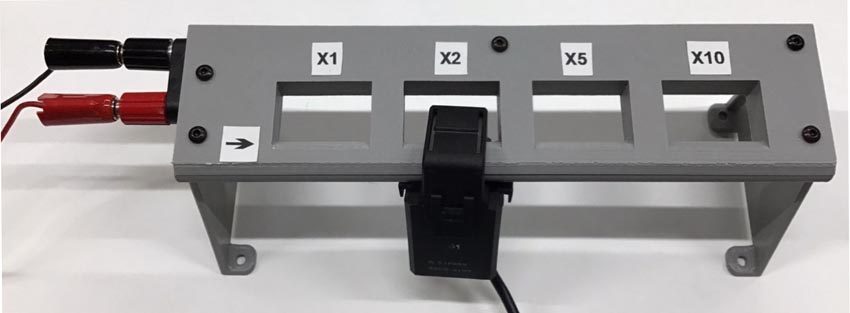
Let’s start with a picture of the final product with a split-core Hall effect sensor clamped on (Figure 1):
 |
|
| Figure 1. | Image of the Hall effect split-core current sensor calibration station with the hall effect sensor clamped on. |
And next the all-important schematic (Figure 2):
 |
|
| Figure 2. | Schematic diagram of calibration station. |
(Ok, it’s not as complex as your cell phone but it can still do something useful… it can do multiplication on an analog signal.)
So, the calibration station consists of is an enclosure with a double banana jack and a length of wire. The rest of the magic is in correctly creating some loops to give us different apparent currents to measure in the Hall effect sensor.
As you see in Figure 1, the enclosure has 4 holes we’ll refer to as boxes. In this example we’ll create 4 unique box windings of 1 loop, 2 loops, 5 oops, and 10 loops. That means with a 2 A input on the banana jacks, the clamped-on Hall effect sensor will measure 2 A, 4 A, 10 A, and 20 A on the various box positions. Above I use the word “loops” loosely as you will see.
Let’s take a look at how to create the loops inside (Figure 3).
 |
|
| Figure 3. | Image showing the how the 24-gauge wire was looped around each box to generate 1, 2, 5, and 10 loops. |
Figure 3 shows the station, with the cover and legs removed, and the internal wiring for the above example. I used about 100 inches of 24-gauge wire. It’s actually landline telephone wire but it’s the same as the individual wires in an ethernet cable. (Although the wire type is not important other than whether it can handle the amps supplied from the power supply and you can fit it in the enclosure.)
Now, the wire starts at the red banana jack. It’s a little hard to see because of the extra wire bunched up, but the wire then drops down into the lower channel below box 1. You can see there is only one wire running across the channel below box one. The sensor clamps around this lower channel so, if you clamp the sensor on the lower channel of box 1, it will only see the magnetic field of 1 wire, so 1x the power supply current. Looking at box 2 we can see the wire first passing across the lower channel under the box. It then wraps around box 2 in a counterclockwise manner. After this wrap box 2 has 2 wires in the lower channel, so a sensor clamped at the box 2 position will see 2x the magnetic field therefore it will register 2x the power supply current. In a similar manner, box 3 will have the wire pass under it in the lower channel and then have 4 counterclockwise wraps made around the box before passing under box 4. The sensor will see 5x the magnetic field on box 3. Box 4 is created in a similar manner but has 9 wraps around its box, so the sensor sees the current in 10 wires for 10x the magnetic field thereby measuring 10x the power supply current. The wire is then connected to the black banana jack.
Now in this example we used 1x, 2x, 5x, and 10x, but you can use anything that works for your needs. One option is to make them all the same, say 5x, then you could calibrate 4 sensors at the same time. In fact, you could wire a number of the calibration stands in series and calibrate 8, 12, 16, etc. at a time. Also note that 10x is not a maximum. It looks like you could get quite a few more wraps on a box.
A few notes:
- I called it a calibration stand so in an actual setup you probably want to put a good, calibrated ammeter, like a 5½ digit lab meter, in line with the calibration stand. Also, if you don’t have a constant current power supply, just use any DC supply with the appropriate series resistor and ammeter in series.
- Files for the 3D printable stand can be found on [1].
- It’s assembled using 6 mm M3 screws and the banana jack is Pomona model 4243 but I suspect other banana jacks will fit. Also, I used hot glue in a few spots to control the wiring.
- There are holes in the legs to allow you to screw it to your bench or a stable base.