Three-phase VCOs (voltage-controlled oscillators) see service in many applications, including power inverters and in electronic-music synthesis as control and modulation sources. A previous Design Idea describes a basis for a simple, three-phase VCO (Reference 1). However, adding a few components enhances the circuit's performance. The original circuit delivers an output of only 600 mV p-p and cannot tolerate substantial loading, especially at low operating frequencies at which the circuit draws the least operating current. Providing ac coupling for the output signals doesn't work well at low frequencies and worsens the loading problem. Finally, the circuit's dc operating point varies with frequency.
The circuit in Figure 1 elegantly overcomes these limitations. The original circuit uses three of six of a CD4069UB hex inverter's subcircuits. One of the spares, IC1A, senses the complete circuit's dc operating point. Resistor R2 provides linear feedback around IC1A, forcing the input voltage at Pin 9 to equal the output transition threshold voltage over a range of operating currents. In other words, the voltage is proportional to the average dc value of the sinusoidal output waveforms.
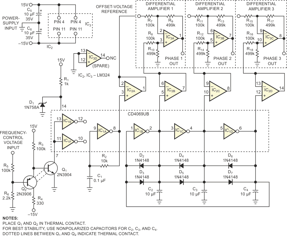 |
|
| Figure 1. | Adding differential and buffer amplifiers and an exponential voltage-to-current converter enhances the performance of a low-frequency, three-phase voltage-controlled oscillator. |
A voltage follower, IC2A, buffers the averaged voltage at IC1A's Pin 8. The remaining sections of IC2 buffer the oscillator's three outputs, equalizing the loading on the oscillator and providing low-impedance drive to three differential amplifiers: IC3A, IC3B, and IC3C. The differential stages subtract the dc offset voltage from IC2A from the buffered three-phase outputs. You can alter the voltage gain of the three differential amplifiers from its nominal factor of five to suit other applications.
Zener diode D1 limits the voltage to 10 V at IC1's Pin 14. At low frequencies and currents, the oscillator's dc operating point can easily exceed the linear range of IC2's inputs. You can use rail-to-rail-capable operational amplifiers instead of LM324-family devices. Note that the inputs of IC1's remaining unused inverters connect to IC1's Pin 7 and not to circuit ground per normal practice.
Adding an exponential current source eases the task of adjusting the circuit over a wide frequency range. Transistors Q1 and Q2 and their associated components form a simple exponential voltage-to-current converter. For best results, the base-emitter voltages of Q1 and Q2 should match at the circuit's nominal operating current – 100 µA – and you should thermally couple both transistors. If your application requires precise thermal tracking, replace R6 with a 2-kΩ temperature-compensating resistor with a coefficient of 3500 ppm/°C, such as a Tel Labs Q81, which is available from such companies as Precision Resistor. Place this resistor in thermal contact with Q1 and Q2. Temperature-compensating resistors are also available from Micro-Ohm, Vishay, Ultronix, and KRL Bantry.
Using the component values in Figure 1, the circuit's operating frequency spans 0.1 to 26 Hz. Adding the components in this Design Idea reduces the circuit's dc operating-point shift from 5.5 V to less than 25 mV over the frequency range. Most of the frequency error occurs at the low end of the frequency range, at which it's the least objectionable.