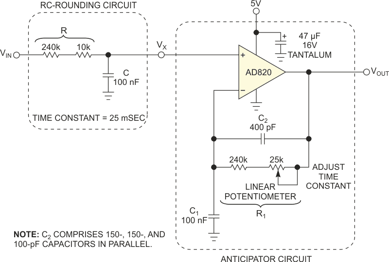
A self-biasing thermistor circuit had an overall dominant thermal/ electrical time constant as small as 25 msec but had a significantly rounded response following a square (thermal) input pulse of 100 msec; the source was a pulsed blue LED. A single-op-amp-based “anticipator-like” circuit generated a more faithful picture of the actual input excitation, and improved on the circuit described in a previous Design Idea (Reference 1). The lowpass filter in Figure 1, with an RC time constant of approximately 25 msec, models the circuit.
 |
|
| Figure 1. | This RC circuit models a single dominant time-constant transducer, producing a rounded, intermediate voltage, VX, in response to an input signal, VIN. With VX as its input, the anticipator circuit reconstructs the original signal from VX, such that VOUT = VIN. |
The input voltage models the stimulus to the transducer – a pulsed thermal flux, say – and the voltage response, VX, at the output of the transducer forms the input to the corrective anticipator circuit, whose output is the voltage signal, VOUT. In the complex frequency, s, you can write the output of the lowpass filter as a function of its input, VIN, in the form of the following well-known equation for a single-pole response:
The single pole of this lowpass response is at frequency
Ignoring for now the 400-pF capacitor in the feedback loop of the circuit of Figure 1, the voltage gain arising from its noninverting op-amp configuration is
Consequently, this response has a single zero at
If you cascade the responses of the RC-rounding transducer and anticipator circuits, then the overall input-to-output system function becomes
Therefore, by choosing the time constant of the anticipator to be equal to that of the transducer – that is, by choosing here C1R1 = CR, pole-zero cancellation occurs in the system function, such that VOUT = VIN.
In other words, the anticipator circuit’s output now becomes identical to the unmodified input stimulus to the transducer. Furthermore, this situation must be true no matter what temporal form the input signal takes.
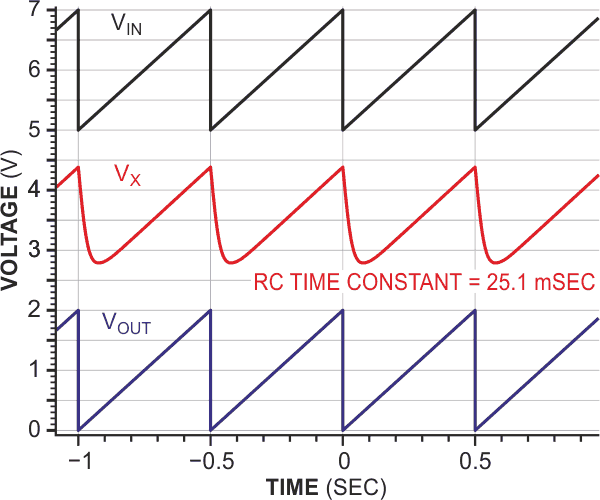
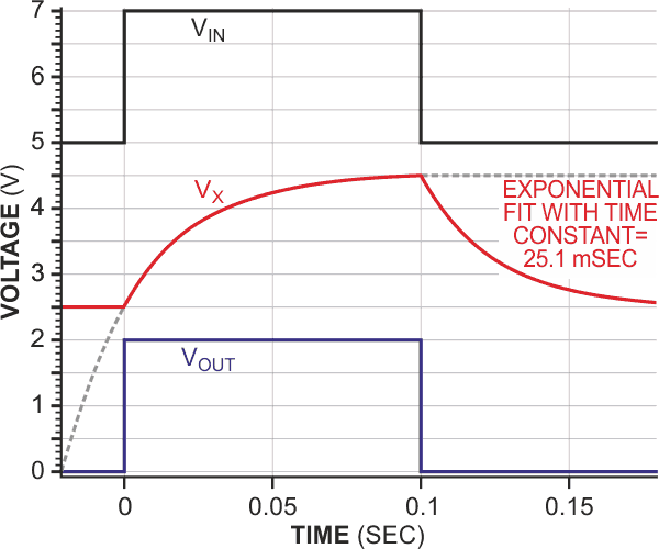
Figures 2, 3, and 4 show an input waveform to the transducer; the corresponding transducer’s output signal; and the final anticipator circuit’s output, which is derived from the available signal, VX. The figures, respectively, show these waveforms for three forms of 2-Hz frequency input: a sawtooth, a pulse input with 20% duty cycle, and a sine-wave input. In each figure, the waveforms for VIN and VX have been offset, vertically, by 5 and 2.5 V, respectively. The sawtooth and sine-wave input signals have 1 V offsets to keep the inputs positive for the single-supply op amp. In practice, a 400-pF capacitor is necessary for optimal stability because it prevents the op amp’s closed-loop gain from tending toward infinity, with rising frequency. Also, although the AD820 is operating in single-supply mode, it can also operate in split-supply mode to handle bipolar signals.
 |
|
| Figure 2. | The reconstruction of the input sawtooth waveform shows that the circuit can operate properly with complex, possibly repetitive waveforms. |
The anticipator circuit performs as you would expect, producing closely equal input and output voltages for all of the tested input waveforms. For more complex, possibly repetitive waveforms, the reconstruction of the input sawtooth waveform provides compelling evidence of the circuit’s proper operation in such a case (Figure ). Like the original circuit, the output of this anticipator jumps immediately to the asymptotic limit of a rising or falling exponential transducer response (Figure 3).
 |
|
| Figure 3. | The output of the anticipator jumps immediately to the asymptotic limit of a rising or falling exponential transducer response. |
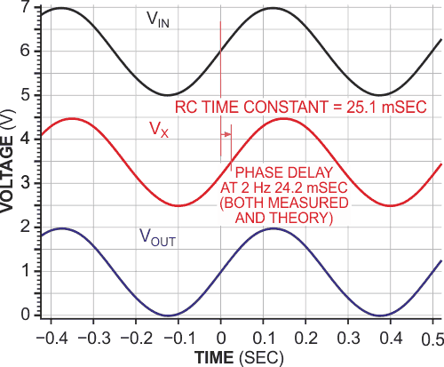
In Figure 4, on the other hand, the transducer-induced phase shift of a sine-wave signal having a single frequency component has been properly back-corrected in time, by −24.2 msec, and the slightly attenuated transducer output – in this case, to 95% of the input amplitude – has been restored at the output to a level of 99.7%. The dc component of the input voltage also has communicated properly and in all cases to the output.
 |
|
| Figure 4. | The transducer-induced phase shift of a sine-wave signal having a single frequency component is properly back-corrected in time, and the slightly attenuated transducer output has been restored at the output. |
An important general caveat is that the intermediate signal, VX, must remain sufficiently large, following the rounding action of the transducer, for the anticipator circuit to accurately reconstruct the input stimulus.