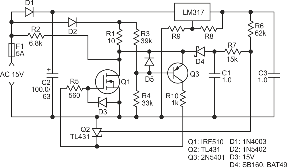
The MOSFET in Figure 1 is used as both a heater and a temperature sensor in a thermostatic circuit.
 |
|
| Figure 1. | Circuit diagram for using a MOSFET as a thermostatic heater. |
The circuit can be used as a tiny thermostat for some biological structures in a Petri dish (typical set temperature is from 30 °C to 50 °C); other uses may include plastic cutting/welding, thermostating of electronic components, and even soft soldering since the maximal working temperature for Si MOSFETs is around 175 °C and, for silicon carbide (SiC), MOSFETs can be far larger.
To function properly in this circuit, the MOSFET Q1 should have a so-called “parasitic” diode within the MOSFET structure (its cathode is connected to the drain of the nFET). Almost all power MOSFETs have this diode within them (in any case you can check its existence in the datasheet). The circuit uses this diode as a temperature sensor (the temperature coefficient is about –2 mV/°C for silicon).
During the negative half-wave of the input AC, while the MOSFET Q1 is OFF, the negative voltage on the “parasitic” diode charges the capacitor C1 through the Schottky diode D3; as a matter of fact, these components create an envelope detector. (This part of the circuit can also be interpreted as an S/H circuit.)
The thing is, the typical direct voltage on a “parasitic” Si diode is 0.3 V to 0.5 V higher than the Schottky’s one, hence the maximal negative voltage on C1 may be about –0.3 V to –0.5 V. Resistors R6 and R7 are part of the envelope detector; they also make a level shift of this negative value to a positive one, making it appropriate for the TL431. To make this possible, the voltage regulator on LM317 provides a positive voltage for this level shift.
The set temperature of the circuit can be changed simply by changing the output voltage of the regulator (varying the values of R8 or R9).
The main role of the resistor R1 is to limit any transient currents to the values which are safe for both MOSFET Q1 and diode D2. Nevertheless, if the application allows, this role can be used broaden to some of the circuit’s functionality: R1 can be used as one more heating spot. You should remember however, this spot will have no thermal sensor inside, so a regulation in its vicinity may be far more crude.
During the following positive half-wave, the negative voltage saved on C1 makes the TL431 determine whether the MOSFET Q1 has to be ON or OFF.
When Q1 is ON, the circuit on the pnp transistor Q3 maintains the drain voltage of Q1 very close to the voltage on R4. This is because both the MOSFET Q1 and the transistor Q3 constitute a negative-feedback amplifier, which determines the operating point of Q1 by the ratio of the values R3 and R4.
As shown in Figure 1, the MOSFET Q1 with resistor R1 – on the one hand – and resistors R3, R4 – on the other hand – make up a bridge circuit, which restores its equilibrium if the drain voltage is ~equal to or close to the base voltage of Q3.
Playing with R3/R4 ratio will allow you to change the ratio of the heat dissipated by Q1 and R1.
When R3 = R4, the electrical powers dissipated on Q1 and R1 are equal; in general R1 can be used as additional heater for a larger object, when Q1 alone can’t provide sufficient heating.
In any case, have in mind the maximal ratings of Q1, D2 and R1.
These relations between time constants should be observed:
(R6 + R7) × C1 >> T/2 >> R1 × C1,
where T stands for period of input AC.
When using the heater for a critical application at high temperatures, caution should be observed since some SiC MOSFETS can be unreliable [1].
Note: since the minimal voltage on TL431 is about 0.9 V to 1 V, the minimal gate threshold voltage of Q1 (at the maximal working temperatures!) should be higher than this value.
Reference
- Lelis, Aivars J., et al. “High-Temperature Reliability of SiC Power MOSFETs.” Materials Science Forum, vol. 679–680, Trans Tech Publications, Ltd., Mar. 2011, pp. 599–602.