REC Johnson, B Lora Narayana, and Devender Sundi, Center for Cellular and Molecular Biology, Hyderabad, India
A temperature sensor and a hot transistor hold biological samples at a preset temperature
It is common to use transistors for driving resistive heating elements. However, you can use the heat that a power transistor dissipates to advantage in several situations, eliminating the need for a separate heating element because most transistors can safely operate at temperatures as high as 100°C. A typical example is in a biological laboratory, in which the need for maintaining the temperature of samples in microliter-sized cuvettes is a common requirement. The space/geometry constraint and the less-than-100°C upper-temperature limit are the basic factors of the idea.
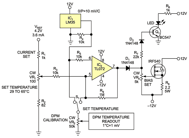
You can use an N-channel IRF540 MOSFET to directly heat and control the temperature of a biological sample from ambient to 45°C. Figure 1 shows a simple on/off-type control circuit in which an LM35, IC1, is the temperature sensor, whose output a DPM (digital panel meter) can display. IC2 compares the voltage that VR1 sets with the output of the LM35 to turn on Q2 accordingly, with the positive feedback through R9 providing a small amount of hysteresis. S1 switches the DPM between a set value and the actual temperature readout. You derive the reference voltage from a TL431 shunt regulator (not shown). The LED lights up when Q2 is on.
 |
|
|
Figure 1. |
IC1 senses the temperature of the item that Q2 heats, and the temperature remains at the level that VR1 sets. |
IC1 and Q2 thermally mount on the metal block that forms the sample holder; use thermal grease on both components for maximum heat transfer. Note that the mounting tab of the TO-220 package electrically connects to the drain, and you may need to insulate it from the cuvette with a thermal pad. Setting bias control VR3 for a Q2 current of 270 mA is sufficient to hold the cuvette at 45°C.
Be sure to set to minimum power during initial power-up; if you set it for maximum power, you could apply 24V to Q2’s gate-to-source voltage, which is rated for a maximum of only 20V. You can extend the temperature range by changing the voltage divider comprising R1, R2, and VR1. The design includes a safety cutoff circuit (not shown) in case the temperature gets too high.
Various other options are also possible applications for this circuit. These applications include linear control, pulse-width modulation, and the use of a PID (proportional-integral-derivative) controller, to name a few.