Many industrial- and medical-system circuits require isolation from the mains-ac power. You can often send a signal across the isolation barrier using a small transformer; transformers do not pass low-frequency signals well. The circuit in this Design Idea converts a low-frequency PWM (pulse-width-modulated) signal to a higher frequency, which you pass across the transformer, and retains the duty cycle. Once the frequency is on the other side, you can then convert the PWM signal back to an analog voltage.
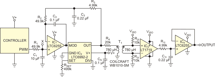
The circuit converts a 1-kHz PWM signal to a 100-kHz signal with the same duty cycle (Figure 1). This 100-kHz signal easily couples across an isolation transformer. You then filter it to provide a dc control voltage on the isolated side. IC2, an LTC6992-2, is a voltage-controlled PWM IC. A voltage ranging from 0 to 1 V on the MOD input pin varies the duty cycle of the output from 5 to 95%. The duty cycle does not reach 0 or 100%, which would not pass through the transformer. Resistor RSET fixes an internal master-oscillator frequency of 100 kHz. The voltage on the DIV pin sets a divider ratio. An internal 4-bit ADC translates the analog voltage to a digital-divider value. With the input shored to ground, the divider ratio is one, and the circuit outputs the oscillator frequency.
 |
|
| Figure 1. | This circuit creates a 100-kHz PWM signal from a 1-kHz PWM signal to send it across an isolation transformer. The output is an integrated dc control voltage. |
R2 and C2 make amplifier IC1 a voltage integrator. It servo-controls the voltage at the MOD pin of IC2. R1 and C1 filter the input signal to an average dc value. The integrator compares this value with the average dc value of the IC2 output that you filter with R3 and C3. This step forces the 100-kHz output signal to the same duty cycle as the 1-kHz input signal. The time constants of these filters should be much longer than the clock period to minimize duty-cycle jitter. You use a 500-msec time-constant network for the 1-kHz PWM signal and a 1-msec time-constant network with the 100-kHz PWM signal. The amplitude of each signal must be the same for an accurate match of the two duty cycles. For this reason, IC2’s power-supply voltage is the same supply the PWM controller uses. Any supply-voltage variation affects each signal in the same way, providing insensitivity to power-supply variation.
IC2 has 20 mA of output current to drive the primary of the isolation transformer, and comparator IC3 squares up the 100-kHz PWM signal on the isolated side of T1. You can use this output directly as a digital-control signal if necessary. In this circuit, you filter the signal with a 1-msec RC lowpass network and then buffer the signal with voltage-follower amplifier IC4, yielding a dc analog-control voltage.
 |
|
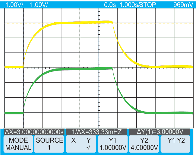
| Figure 2. | The circuit gives a gradual exponential response to a 20 to 80% step change in duty cycle. A 500-msec time constant filters the input PWM (yellow). The filtered, 100-kHz isolated signal closely matches the input (green). |
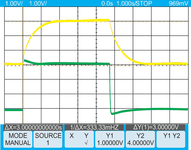
The circuit accurately replicates a stepped increase in the input PWM duty cycle (Figure 2). The circuit operates from a 5 V supply. The average voltage changes from 1 to 4 V when you change the input duty cycle from 20 to 80%. The slow change is due to the 500-msec time-constant filter, an acceptable scenario in cases in which a gradual change in the isolated control signal is acceptable. You can circumvent the slow response at the expense of some overshoot if you need a faster response. For this task, you use an anticipator circuit, as a previous Design Idea describes (Reference 1). Adding the anticipator circuit at the X node of Figure 1 results in a faster response to a final value (Figure 3).
 |
|
| Figure 3. | An anticipator circuit speeds the output response (green). |
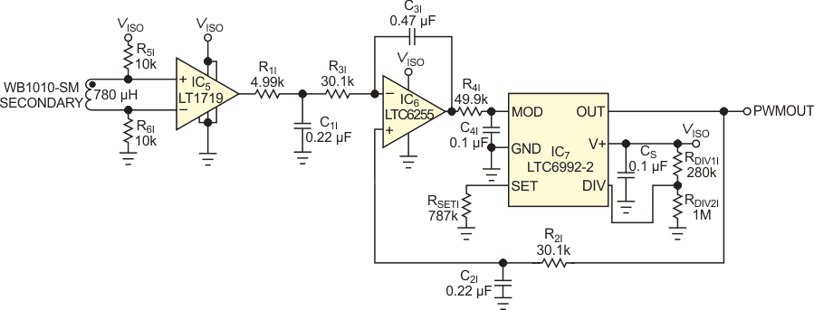
You add another voltage-controlled PWM IC to re-create the 1-kHz PWM signal on the isolated side (Figure 4). You use amplifier-integrator circuit IC6 to servo-control the duty cycle of IC7. Resistor RSETI programs IC7 for 1-kHz, 5- to 95%-duty-cycle operation. The circuit forces the 1-kHz output duty cycle to equal the 100-kHz input-signal duty cycle. Again, the supply voltage for comparator IC5 and the PWM device must be the same. If you want minimum duty-cycle ripple, set filter R2I and C2I to have a 500-msec time constant. Unfortunately, this approach would make the response time of the reconstructed output slow. You cannot use the anticipator circuit when you re-create the slow PWM signal because the slow signal is now the dependent variable in the circuit, and fast jumps in the feedback voltage would result in the loop’s continuously hunting and never settling to a final value. Use instead a 10-msec time-constant filter on the 1-kHz output to obtain a reasonable response time and then minimize duty-cycle ripple with an additional lowpass network comprising R4I and C4I.
 |
|
| Figure 4. | This circuit re-creates the 1-kHz PWM control signal on the isolated side. It cannot use the anticipator circuit, but R4I and C4I provide extra lowpass filtering, helping to reduce output jitter. |
Note that the feedback signal for integrator IC1 in Figure 1 is on the negative pin and that the feedback signal to recreation integrator IC6 is on the positive pin. If you connect the fast-responding input signal to the positive input of IC6, it would cause a large overshoot in the duty cycle of the output signal and a long recovery time. You compensate for the polarity reversal by biasing the DIV pin of IC2.
Setting the DIV pin above VSUPPLY/2 programs the output-control polarity to change from 95 to 5% duty cycle with an increasing voltage applied to the MOD pin. An increase in the 100-kHz signal’s duty cycle now ramps down the MOD pin and increases the 1-kHz output signal’s duty cycle to match it.
Reference
Materials on the topic
- Datasheet Analog Devices LT1719
- Datasheet Analog Devices LT6255
- Datasheet Analog Devices LTC6992-2
- Datasheet Coilcraft WB1010-SM