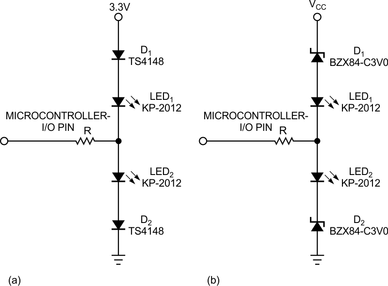
The basis for this Design Idea is a circuit that uses three resistors and a microcontroller-I/O pin to work as input high impedance or output to independently drive two LEDs (Reference 1). The idea sounded good for this design, mainly because of the lack of spare I/O pins in the microcontroller and the simplicity of the implementation. Unfortunately, you cannot use the circuit in battery-powered designs because it exhibits a current leakage on the order of 2 mA even with both LEDs off. This Design Idea modifies that circuit, using only one I/O pin to drive the two LEDs but with a low current drain (Figure 1). Although the circuit uses a couple of diodes and a resistor, the price and the component count are low.
 |
|
| Figure 1. | In these simple circuits, the LEDs need a voltage of approximately 1.5 V (a) or more than 5 V (b) to turn on. The circuits allow a battery-powered microcontroller to control two LEDs with only one I/O pin. |
The basis for the operation of both circuits is the nonlinear characteristic of a diode, in which current grows exponentially with the voltage applied across it. To describe the operation, suppose that the microcontroller pin is configured as an input, leaving the pin in high impedance. In the first circuit, assume that LEDs need a voltage of approximately 1.5 V to turn on and that the small-signal-diode voltage drop is approximately 0.6 V (Figure 1a). So, to turn on both LEDs, you theoretically need 4.2 V. In practice, the LEDs start dimming at approximately 4 V with a current of 80 µA and are fully on with 4.4 V at a current of 1 mA. With 3.3 V, leakage current is merely 2.41 µA. The nominal voltage for this circuit can be slightly lower than 3.3 V, but, in that case, you should use Schottky diodes.
The second circuit is for supply voltages greater than 5 V (Figure 1b). Using the values in the Figure 1b, the LEDs start dimming with 7 V at 74-µA current and are fully on with 8.5 V at 1 mA, remaining off for a 5 V supply at 1.53 µA. To turn on the LEDs, you must configure the microcontroller’s I/O pin as an output; an output value of one turns on the lower LED, and a value of zero turns on the upper LED. If both LEDs must appear to be on, your program can cycle the port pin between one and zero with a frequency greater than 50 Hz. To calculate the value of the resistor, the following formulas apply for Figure 1a:

and for Figure 1b:
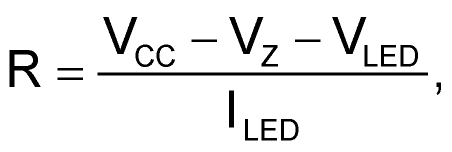
here ILED is the desired LED-on current, VD is the voltage across the diode when an ILED current flows through it, VZ is the zener-diode voltage, and VLED is the forward voltage across the LED when an ILED current flows through it. You should use a Schmitt trigger or an analog input for the I/O pin to avoid excessive current draw.
Reference
- Pefhany, Spehro, “Circuit Controls Two LEDs With One Microcontroller Port Pin.”