Semiconductor laser diodes (SLDs) are often packaged with a photodiode. The output current from this photodiode can be monitored to regulate the output power intensity of the laser diode. SLDs, however, are prone to pathological drifts, such as temperature variations and mode-hopping, that can alter the output intensity. A popular approach to stabilize the output intensity is to first convert the photodiode current to voltage. This voltage can then be read by a microcontroller, where logic can be programmed to adjust the current supplied to the laser diode. This method is illustrated in Figure 1.
 |
|
| Figure 1. | Using a microcontroller to regulate laser diode output power by sensing photodiode current. |
Figure 2 provides an alternative implementation that uses a single operational amplifier. When the circuit is powered on, there is initially no photodiode current. The voltage at the positive input of the op-amp is pulled to VCC, and the op-amp powers the laser diode. This induces current in the photodiode, which creates a voltage drop across R1, setting the positive input of the op-amp to: VCC – IPHOTODIODE × R1.
 |
|
| Figure 2. | A single op-amp solution using negative feedback to provide output power regulation. |
The op-amp buffers this voltage and feeds it to the laser diode. The system stabilizes at an operating point determined by:
- The laser diode’s VI-intensity curve
- The coupling efficiency between the laser diode and photodiode
- The current-intensity response of the photodiode
- R1
Thereafter, negative feedback stabilizes any variations in output intensity. If the laser intensity increases, the photodiode responds by generating a higher current, which in turn creates a larger voltage drop across R1. This reduces the output voltage of the op-amp, subsequently decreasing the laser intensity. The opposite behavior is seen with a drop in laser output power.
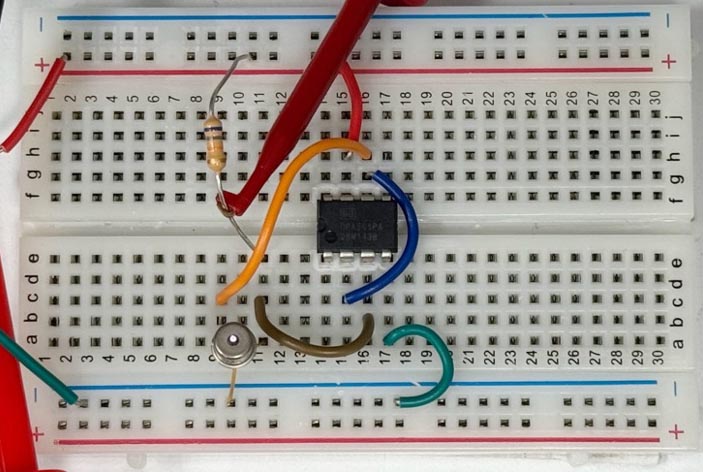
This circuit was built on a breadboard using the OPV314 850-nm VCSEL and the OPA551P op-amp from Texas Instruments (Figure 3). R1 was set to 68 kΩ, and VCC was set to 5 V.
 |
|
| Figure 3. | Components assembled on a breadboard using the OPV314 850-nm VCSEL and the OPA551P op-amp. |
The oscilloscope trace captured from the positive node of the op-amp is shown in Figure 4, demonstrating the stable output from the laser (arbitrary units). R1 can be used to control the output power intensity.
 |
|
| Figure 4. | Oscilloscope trace of positive node of op-amp (proxy for output laser intensity). |